The lowest addresses in the program memory space are by default defined as the Reset and
Interrupt Vectors. The complete list of vectors is shown in “Interrupts” on page 57. The list also
determines the priority levels of the different interrupts. The lower the address the higher is the
priority level. RESET has the highest priority, and next is ANACOMP0 – the Analog Comparator
0 Interrupt. The Interrupt Vectors can be moved to the start of the Boot Flash section by setting
the IVSEL bit in the MCU Control Register (MCUCR). Refer to “Interrupts” on page 57 for more
information. The Reset Vector can also be moved to the start of the Boot Flash section by pro-
gramming the BOOTRST Fuse, see “Boot Loader Support – Read-While-Write
Self-Programming ATmega16/32/64/M1/C1” on page 279.
3.8.1
Interrupt Behavior
When an interrupt occurs, the Global Interrupt Enable I-bit is cleared and all interrupts are dis-
abled. The user software can write logic one to the I-bit to enable nested interrupts. All enabled
interrupts can then interrupt the current interrupt routine. The I-bit is automatically set when a
Return from Interrupt instruction – RETI – is executed.
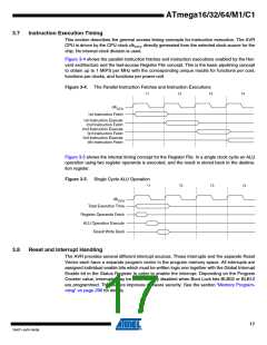
There are basically two types of interrupts. The first type is triggered by an event that sets the
interrupt flag. For these interrupts, the Program Counter is vectored to the actual Interrupt Vector
in order to execute the interrupt handling routine, and hardware clears the corresponding inter-
rupt flag. Interrupt flags can also be cleared by writing a logic one to the flag bit position(s) to be
cleared. If an interrupt condition occurs while the corresponding interrupt enable bit is cleared,
the interrupt flag will be set and remembered until the interrupt is enabled, or the flag is cleared
by software. Similarly, if one or more interrupt conditions occur while the Global Interrupt Enable
bit is cleared, the corresponding interrupt flag(s) will be set and remembered until the Global
Interrupt Enable bit is set, and will then be executed by order of priority.
The second type of interrupts will trigger as long as the interrupt condition is present. These
interrupts do not necessarily have interrupt flags. If the interrupt condition disappears before the
interrupt is enabled, the interrupt will not be triggered.
When the AVR exits from an interrupt, it will always return to the main program and execute one
more instruction before any pending interrupt is served.
Note that the Status Register is not automatically stored when entering an interrupt routine, nor
restored when returning from an interrupt routine. This must be handled by software.
When using the CLI instruction to disable interrupts, the interrupts will be immediately disabled.
No interrupt will be executed after the CLI instruction, even if it occurs simultaneously with the
CLI instruction. The following example shows how this can be used to avoid interrupts during the
timed EEPROM write sequence.
18
ATmega16/32/64/M1/C1
7647F–AVR–04/09

 ATMEL [ ATMEL ]