Reading the 16-bit value in the Input Capture Register (ICR1) is done by first reading the
Low byte (ICR1L) and then the High byte (ICR1H). When the Low byte is read the High
byte is copied into the High byte temporary register (TEMP). When the CPU reads the
ICR1H I/O location it will access the TEMP Register.
The ICR1 Register can only be written when using a Waveform Generation mode that
utilizes the ICR1 Register for defining the counter’s TOP value. In these cases the
Waveform Generation mode (WGM13:0) bits must be set before the TOP value can be
written to the ICR1 Register. When writing the ICR1 Register the High byte must be writ-
ten to the ICR1H I/O location before the Low byte is written to ICR1L.
For more information on how to access the 16-bit registers refer to “Accessing 16-bit
Registers” on page 77.
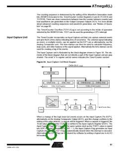
Input Capture Trigger Source The main trigger source for the Input Capture unit is the Input Capture Pin (ICP1).
Timer/Counter 1 can alternatively use the Analog Comparator Output as trigger source
for the Input Capture unit. The Analog Comparator is selected as trigger source by set-
ting the Analog Comparator Input Capture (ACIC) bit in the Analog Comparator Control
and Status Register (ACSR). Be aware that changing trigger source can trigger a cap-
ture. The Input Capture Flag must therefore be cleared after the change.
Both the Input Capture Pin (ICP1) and the Analog Comparator Output (ACO) inputs are
sampled using the same technique as for the T1 pin (Figure 30 on page 72). The edge
detector is also identical. However, when the noise canceler is enabled, additional logic
is inserted before the edge detector, which increases the delay by four system clock
cycles. Note that the input of the noise canceler and edge detector is always enabled
unless the Timer/Counter is set in a Waveform Generation mode that uses ICR1 to
define TOP.
An Input Capture can be triggered by software by controlling the port of the ICP1 pin.
Noise Canceler
The noise canceler improves noise immunity by using a simple digital filtering scheme.
The noise canceler input is monitored over four samples, and all four must be equal for
changing the output that in turn is used by the edge detector.
The noise canceler is enabled by setting the Input Capture Noise Canceler (ICNC1) bit
in Timer/Counter Control Register B (TCCR1B). When enabled the noise canceler intro-
duces additional four system clock cycles of delay from a change applied to the input, to
the update of the ICR1 Register. The noise canceler uses the system clock and is there-
fore not affected by the prescaler.
Using the Input Capture Unit
The main challenge when using the Input Capture unit is to assign enough processor
capacity for handling the incoming events. The time between two events is critical. If the
processor has not read the captured value in the ICR1 Register before the next event
occurs, the ICR1 will be overwritten with a new value. In this case the result of the cap-
ture will be incorrect.
When using the Input Capture interrupt, the ICR1 Register should be read as early in the
interrupt handler routine as possible. Even though the Input Capture interrupt has rela-
tively high priority, the maximum interrupt response time is dependent on the maximum
number of clock cycles it takes to handle any of the other interrupt requests.
Using the Input Capture unit in any mode of operation when the TOP value (resolution)
is actively changed during operation, is not recommended.
Measurement of an external signal’s duty cycle requires that the trigger edge is changed
after each capture. Changing the edge sensing must be done as early as possible after
the ICR1 Register has been read. After a change of the edge, the Input Capture Flag
82
ATmega8(L)
2486M–AVR–12/03

 ATMEL [ ATMEL ]