ATmega8(L)
The counting sequence is determined by the setting of the Waveform Generation mode
bits (WGM13:0) located in the Timer/Counter Control Registers A and B (TCCR1A and
TCCR1B). There are close connections between how the counter behaves (counts) and
how waveforms are generated on the Output Compare Outputs OC1x. For more details
about advanced counting sequences and waveform generation, see “Modes of Opera-
tion” on page 86.
The Timer/Counter Overflow (TOV1) fLag is set according to the mode of operation
selected by the WGM13:0 bits. TOV1 can be used for generating a CPU interrupt.
Input Capture Unit
The Timer/Counter incorporates an Input Capture unit that can capture external events
and give them a time-stamp indicating time of occurrence. The external signal indicating
an event, or multiple events, can be applied via the ICP1 pin or alternatively, via the
Analog Comparator unit. The time-stamps can then be used to calculate frequency,
duty-cycle, and other features of the signal applied. Alternatively the time-stamps can be
used for creating a log of the events.
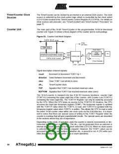
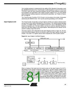
The Input Capture unit is illustrated by the block diagram shown in Figure 34. The ele-
ments of the block diagram that are not directly a part of the Input Capture unit are gray
shaded. The small “n” in register and bit names indicates the Timer/Counter number.
Figure 34. Input Capture Unit Block Diagram
DATA BUS (8-bit)
TEMP (8-bit)
ICRnH (8-bit)
ICRnL (8-bit)
TCNTnH (8-bit)
TCNTnL (8-bit)
ICRn (16-bit Register)
TCNTn (16-bit Counter)
WRITE
ACO*
ACIC*
ICNC
ICES
Analog
Comparator
Noise
Canceler
Edge
Detector
ICFn (Int. Req.)
ICPn
When a change of the logic level (an event) occurs on the Input Capture Pin (ICP1),
alternatively on the Analog Comparator Output (ACO), and this change confirms to the
setting of the edge detector, a capture will be triggered. When a capture is triggered, the
16-bit value of the counter (TCNT1) is written to the Input Capture Register (ICR1). The
Input Capture Flag (ICF1) is set at the same system clock as the TCNT1 value is copied
into ICR1 Register. If enabled (TICIE1 = 1), the Input Capture Flag generates an Input
Capture interrupt. The ICF1 Flag is automatically cleared when the interrupt is executed.
Alternatively the ICF1 Flag can be cleared by software by writing a logical one to its I/O
bit location.
81
2486M–AVR–12/03

 ATMEL [ ATMEL ]