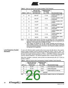
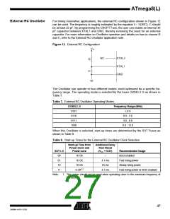
External Clock
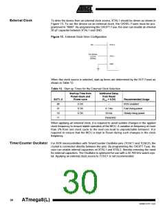
To drive the device from an external clock source, XTAL1 should be driven as shown in
Figure 13. To run the device on an external clock, the CKSEL Fuses must be pro-
grammed to “0000”. By programming the CKOPT Fuse, the user can enable an internal
36 pF capacitor between XTAL1 and GND.
Figure 13. External Clock Drive Configuration
EXTERNAL
CLOCK
SIGNAL
When this clock source is selected, start-up times are determined by the SUT Fuses as
shown in Table 12.
Table 12. Start-up Times for the External Clock Selection
Start-up Time from
Power-down and
Power-save
Additional Delay
from Reset
SUT1..0
00
(VCC = 5.0V)
Recommended Usage
BOD enabled
6 CK
6 CK
6 CK
–
01
4.1 ms
65 ms
Reserved
Fast rising power
Slowly rising power
10
11
When applying an external clock, it is required to avoid sudden changes in the applied
clock frequency to ensure stable operation of the MCU. A variation in frequency of more
than 2% from one clock cycle to the next can lead to unpredictable behavior. It is
required to ensure that the MCU is kept in Reset during such changes in the clock
frequency.
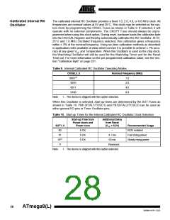
Timer/Counter Oscillator For AVR microcontrollers with Timer/Counter Oscillator pins (TOSC1 and TOSC2), the
crystal is connected directly between the pins. By programming the CKOPT Fuse, the
user can enable internal capacitors on XTAL1 and XTAL2, thereby removing the need
for external capacitors. The Oscillator is optimized for use with a 32.768 kHz watch crys-
tal. Applying an external clock source to TOSC1 is not recommended.
30
ATmega8(L)
2486M–AVR–12/03

 ATMEL [ ATMEL ]