ATmega8(L)
Oscillator Calibration Register
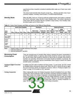
– OSCCAL
Bit
7
6
5
4
3
2
1
0
CAL7
R/W
CAL6
R/W
CAL5
R/W
CAL4
R/W
CAL3
R/W
CAL2
R/W
CAL1
R/W
CAL0
R/W
OSCCAL
Read/Write
Initial Value
Device Specific Calibration Value
• Bits 7..0 – CAL7..0: Oscillator Calibration Value
Writing the calibration byte to this address will trim the Internal Oscillator to remove pro-
cess variations from the Oscillator frequency. During Reset, the 1 MHz calibration value
which is located in the signature row High byte (address 0x00) is automatically loaded
into the OSCCAL Register. If the internal RC is used at other frequencies, the calibration
values must be loaded manually. This can be done by first reading the signature row by
a programmer, and then store the calibration values in the Flash or EEPROM. Then the
value can be read by software and loaded into the OSCCAL Register. When OSCCAL is
zero, the lowest available frequency is chosen. Writing non-zero values to this register
will increase the frequency of the Internal Oscillator. Writing 0xFF to the register gives
the highest available frequency. The calibrated Oscillator is used to time EEPROM and
Flash access. If EEPROM or Flash is written, do not calibrate to more than 10% above
the nominal frequency. Otherwise, the EEPROM or Flash write may fail. Note that the
Oscillator is intended for calibration to 1.0, 2.0, 4.0, or 8.0 MHz. Tuning to other values is
not guaranteed, as indicated in Table 11.
Table 11. Internal RC Oscillator Frequency Range
Min Frequency in Percentage of
Nominal Frequency (%)
Max Frequency in Percentage of
Nominal Frequency (%)
OSCCAL Value
0x00
50
75
100
150
200
0x7F
0xFF
100
29
2486M–AVR–12/03

 ATMEL [ ATMEL ]