ATmega8(L)
Sp
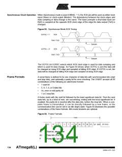
Stop bit, always high.
IDLE No transfers on the communication line (RxD or TxD). An IDLE line must be
high.
The frame format used by the USART is set by the UCSZ2:0, UPM1:0 and USBS bits in
UCSRB and UCSRC. The Receiver and Transmitter use the same setting. Note that
changing the setting of any of these bits will corrupt all ongoing communication for both
the Receiver and Transmitter.
The USART Character SiZe (UCSZ2:0) bits select the number of data bits in the frame.
The USART Parity mode (UPM1:0) bits enable and set the type of parity bit. The selec-
tion between one or two stop bits is done by the USART Stop Bit Select (USBS) bit. The
Receiver ignores the second stop bit. An FE (Frame Error) will therefore only be
detected in the cases where the first stop bit is zero.
Parity Bit Calculation
The parity bit is calculated by doing an exclusive-or of all the data bits. If odd parity is
used, the result of the exclusive or is inverted. The relation between the parity bit and
data bits is as follows:
P
P
= d
= d
…
…
d
d
d
d
d
d
d
d
0
1
even
n – 1
n – 1
3
3
2
2
1
1
0
0
odd
Peven Parity bit using even parity.
Podd
dn
Parity bit using odd parity.
Data bit n of the character.
If used, the parity bit is located between the last data bit and first stop bit of a serial
frame.
USART Initialization
The USART has to be initialized before any communication can take place. The initial-
ization process normally consists of setting the baud rate, setting frame format and
enabling the Transmitter or the Receiver depending on the usage. For interrupt driven
USART operation, the Global Interrupt Flag should be cleared (and interrupts globally
disabled) when doing the initialization.
Before doing a re-initialization with changed baud rate or frame format, be sure that
there are no ongoing transmissions during the period the registers are changed. The
TXC Flag can be used to check that the Transmitter has completed all transfers, and the
RXC Flag can be used to check that there are no unread data in the receive buffer. Note
that the TXC Flag must be cleared before each transmission (before UDR is written) if it
is used for this purpose.
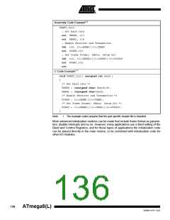
The following simple USART initialization code examples show one assembly and one
C function that are equal in functionality. The examples assume asynchronous opera-
tion using polling (no interrupts enabled) and a fixed frame format. The baud rate is
given as a function parameter. For the assembly code, the baud rate parameter is
assumed to be stored in the r17:r16 Registers. When the function writes to the UCSRC
Register, the URSEL bit (MSB) must be set due to the sharing of I/O location by UBRRH
and UCSRC.
135
2486M–AVR–12/03

 ATMEL [ ATMEL ]