ATmega8(L)
• Bit 4 – FE: Frame Error
This bit is set if the next character in the receive buffer had a Frame Error when received (that is,
when the first stop bit of the next character in the receive buffer is zero). This bit is valid until the
receive buffer (UDR) is read. The FE bit is zero when the stop bit of received data is one. Always
set this bit to zero when writing to UCSRA.
• Bit 3 – DOR: Data OverRun
This bit is set if a Data OverRun condition is detected. A Data OverRun occurs when the receive
buffer is full (two characters), it is a new character waiting in the Receive Shift Register, and a
new start bit is detected. This bit is valid until the receive buffer (UDR) is read. Always set this bit
to zero when writing to UCSRA.
• Bit 2 – PE: Parity Error
This bit is set if the next character in the receive buffer had a Parity Error when received and the
parity checking was enabled at that point (UPM1 = 1). This bit is valid until the receive buffer
(UDR) is read. Always set this bit to zero when writing to UCSRA.
• Bit 1 – U2X: Double the USART transmission speed
This bit only has effect for the asynchronous operation. Write this bit to zero when using syn-
chronous operation.
Writing this bit to one will reduce the divisor of the baud rate divider from 16 to 8 effectively dou-
bling the transfer rate for asynchronous communication.
• Bit 0 – MPCM: Multi-processor Communication Mode
This bit enables the Multi-processor Communication mode. When the MPCM bit is written to
one, all the incoming frames received by the USART Receiver that do not contain address infor-
mation will be ignored. The Transmitter is unaffected by the MPCM setting. For more detailed
information see “Multi-processor Communication Mode” on page 145.
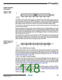
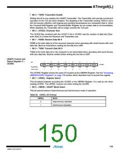
USART Control and
Status Register B –
UCSRB
Bit
7
RXCIE
R/W
0
6
TXCIE
R/W
0
5
UDRIE
R/W
0
4
RXEN
R/W
0
3
TXEN
R/W
0
2
UCSZ2
R/W
0
1
RXB8
R
0
TXB8
R/W
0
UCSRB
Read/Write
Initial Value
0
• Bit 7 – RXCIE: RX Complete Interrupt Enable
Writing this bit to one enables interrupt on the RXC Flag. A USART Receive Complete interrupt
will be generated only if the RXCIE bit is written to one, the Global Interrupt Flag in SREG is writ-
ten to one and the RXC bit in UCSRA is set.
• Bit 6 – TXCIE: TX Complete Interrupt Enable
Writing this bit to one enables interrupt on the TXC Flag. A USART Transmit Complete interrupt
will be generated only if the TXCIE bit is written to one, the Global Interrupt Flag in SREG is writ-
ten to one and the TXC bit in UCSRA is set.
• Bit 5 – UDRIE: USART Data Register Empty Interrupt Enable
Writing this bit to one enables interrupt on the UDRE Flag. A Data Register Empty interrupt will
be generated only if the UDRIE bit is written to one, the Global Interrupt Flag in SREG is written
to one and the UDRE bit in UCSRA is set.
• Bit 4 – RXEN: Receiver Enable
Writing this bit to one enables the USART Receiver. The Receiver will override normal port oper-
ation for the RxD pin when enabled. Disabling the Receiver will flush the receive buffer
invalidating the FE, DOR and PE Flags.
149
2486AA–AVR–02/2013

 ATMEL [ ATMEL ]