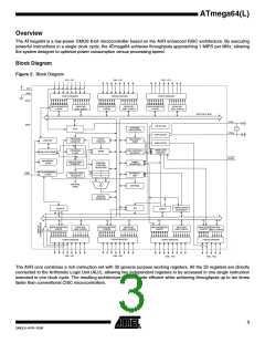
ATmega64(L)
RESET
Reset input. A low level on this pin for longer than the minimum pulse length will gener-
ate a reset, even if the clock is not running. The minimum pulse length is given in Table
19 on page 53. Shorter pulses are not guaranteed to generate a reset.
XTAL1
XTAL2
AVCC
Input to the inverting Oscillator amplifier and input to the internal clock operating circuit.
Output from the inverting Oscillator amplifier.
AVCC is the supply voltage pin for Port F and the A/D Converter. It should be externally
connected to VCC, even if the ADC is not used. If the ADC is used, it should be con-
nected to VCC through a low-pass filter.
AREF
PEN
AREF is the analog reference pin for the A/D Converter.
This is a programming enable pin for the SPI Serial Programming mode. By holding this
pin low during a Power-on Reset, the device will enter the SPI Serial Programming
mode. PEN has no function during normal operation.
Resources
A comprehensive set of development tools, application notes and datasheetsare avail-
able for download on http://www.atmel.com/avr.
7
2490LS–AVR–10/06

 ATMEL [ ATMEL ]