ATmega48/88/168
USART Control and Status
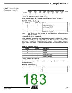
Register n C – UCSRnC
Bit
7
UMSELn1
R/W
6
UMSELn0
R/W
5
UPMn1
R/W
0
4
UPMn0
R/W
0
3
USBSn
R/W
0
2
UCSZn1
R/W
1
UCSZn0
R/W
0
UCPOLn
R/W
UCSRnC
Read/Write
Initial Value
0
0
1
1
0
• Bits 7:6 – UMSELn1:0 USART Mode Select
These bits select the mode of operation of the USARTn as shown in Table 76.
Table 76. UMSELn Bits Settings
UMSELn1
UMSELn0
Mode
0
0
1
1
0
1
0
1
Asynchronous USART
Synchronous USART
(Reserved)
Master SPI (MSPIM)(1)
Note:
1. See “USART in SPI Mode” on page 189 for full description of the Master SPI Mode
(MSPIM) operation
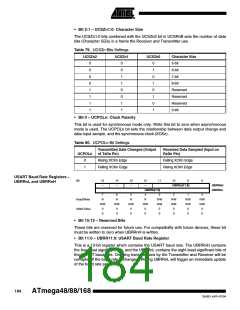
• Bits 5:4 – UPMn1:0: Parity Mode
These bits enable and set type of parity generation and check. If enabled, the Transmit-
ter will automatically generate and send the parity of the transmitted data bits within
each frame. The Receiver will generate a parity value for the incoming data and com-
pare it to the UPMn setting. If a mismatch is detected, the UPEn Flag in UCSRnA will be
set.
Table 77. UPMn Bits Settings
UPMn1
UPMn0
Parity Mode
0
0
1
1
0
1
0
1
Disabled
Reserved
Enabled, Even Parity
Enabled, Odd Parity
• Bit 3 – USBSn: Stop Bit Select
This bit selects the number of stop bits to be inserted by the Transmitter. The Receiver
ignores this setting.
Table 78. USBS Bit Settings
USBSn
Stop Bit(s)
1-bit
0
1
2-bit
183
2545D–AVR–07/04

 ATMEL [ ATMEL ]