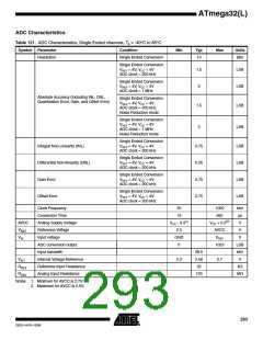
ATmega32(L)
6] The sum of all IOH, for ports C0 - C7, should not exceed 100 mA.If IOH exceeds the test condition, VOH may exceed the
related specification. Pins are not guaranteed to source current greater than the listed test condition.
5. Minimum VCC for Power-down is 2.5V.
External Clock Drive
Figure 144. External Clock Drive Waveforms
Waveforms
V
IH1
V
IL1
External Clock Drive
Table 117. External Clock Drive
VCC = 2.7V to 5.5V
VCC = 4.5V to 5.5V
Symbol
1/tCLCL
tCLCL
Parameter
Oscillator Frequency
Clock Period
High Time
Min
0
Max
Min
0
Max
Units
MHz
ns
8
16
125
50
62.5
25
tCHCX
tCLCX
ns
Low Time
50
25
ns
tCLCH
Rise Time
1.6
1.6
0.5
0.5
μs
tCHCL
Fall Time
μs
Change in period from
one clock cycle to the
next
2
2
ꢀ
ΔtCLCL
Table 118. External RC Oscillator, Typical Frequencies (VCC = 5V)
R [kΩ](1)
C [pF]
22
f(2)
33
650 kHz
2.0 MHz
10
22
Notes: 1. R should be in the range 3 kΩ - 100 kΩ, and C should be at least 20 pF. The C values
given in the table includes pin capacitance. This will vary with package type.
2. The frequency will vary with package type and board layout.
289
2503J–AVR–10/06

 ATMEL [ ATMEL ]