3. A data byte has been received in Master Receiver or Slave Receiver mode.
By writing the TWEA bit to zero, the device can be virtually disconnected from the 2-wire
Serial Bus temporarily. Address recognition can then be resumed by writing the TWEA
bit to one again.
• Bit 5 – TWSTA: TWI START Condition Bit
The application writes the TWSTA bit to one when it desires to become a Master on the
2-wire Serial Bus. The TWI hardware checks if the bus is available, and generates a
START condition on the bus if it is free. However, if the bus is not free, the TWI waits
until a STOP condition is detected, and then generates a new START condition to claim
the bus Master status. TWSTA must be cleared by software when the START condition
has been transmitted.
• Bit 4 – TWSTO: TWI STOP Condition Bit
Writing the TWSTO bit to one in Master mode will generate a STOP condition on the 2-
wire Serial Bus. When the STOP condition is executed on the bus, the TWSTO bit is
cleared automatically. In Slave mode, setting the TWSTO bit can be used to recover
from an error condition. This will not generate a STOP condition, but the TWI returns to
a well-defined unaddressed Slave mode and releases the SCL and SDA lines to a high
impedance state.
• Bit 3 – TWWC: TWI Write Collision Flag
The TWWC bit is set when attempting to write to the TWI Data Register – TWDR when
TWINT is low. This flag is cleared by writing the TWDR Register when TWINT is high.
• Bit 2 – TWEN: TWI Enable Bit
The TWEN bit enables TWI operation and activates the TWI interface. When TWEN is
written to one, the TWI takes control over the I/O pins connected to the SCL and SDA
pins, enabling the slew-rate limiters and spike filters. If this bit is written to zero, the TWI
is switched off and all TWI transmissions are terminated, regardless of any ongoing
operation.
• Bit 1 – Res: Reserved Bit
This bit is a reserved bit and will always read as zero.
• Bit 0 – TWIE: TWI Interrupt Enable
When this bit is written to one, and the I-bit in SREG is set, the TWI interrupt request will
be activated for as long as the TWINT Flag is high.
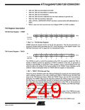
TWI Status Register – TWSR
Bit
7
TWS7
R
6
TWS6
R
5
TWS5
R
4
TWS4
R
3
TWS3
R
2
–
1
TWPS1
R/W
0
0
TWPS0
R/W
0
TWSR
Read/Write
Initial Value
R
0
1
1
1
1
1
• Bits 7..3 – TWS: TWI Status
These 5 bits reflect the status of the TWI logic and the 2-wire Serial Bus. The different
status codes are described later in this section. Note that the value read from TWSR
contains both the 5-bit status value and the 2-bit prescaler value. The application
250
ATmega640/1280/1281/2560/2561
2549A–AVR–03/05

 ATMEL [ ATMEL ]