ATmega640/1280/1281/2560/2561
When the SPI is enabled, the data direction of the MOSI, MISO, SCK, and SS pins is
overridden according to Table 93. For more details on automatic port overrides, refer to
“Alternate Port Functions” on page 86.
Table 93. SPI Pin Overrides(1)
Pin
MOSI
MISO
SCK
SS
Direction, Master SPI
User Defined
Input
Direction, Slave SPI
Input
User Defined
Input
User Defined
User Defined
Input
Note:
1. See “Alternate Functions of Port B” on page 89 for a detailed description of how to
define the direction of the user defined SPI pins.
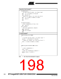
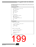
The following code examples show how to initialize the SPI as a Master and how to per-
form a simple transmission. DDR_SPI in the examples must be replaced by the actual
Data Direction Register controlling the SPI pins. DD_MOSI, DD_MISO and DD_SCK
must be replaced by the actual data direction bits for these pins. E.g. if MOSI is placed
on pin PB5, replace DD_MOSI with DDB5 and DDR_SPI with DDRB.
197
2549A–AVR–03/05

 ATMEL [ ATMEL ]