ATmega16(L)
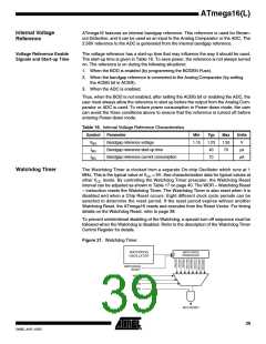
Figure 15. Reset Logic
DATA BUS
MCU Control and Status
Register (MCUCSR)
Power-on
Reset Circuit
Brown-out
Reset Circuit
BODEN
BODLEVEL
Pull-up Resistor
SPIKE
FILTER
Reset Circuit
JTAG Reset
Register
Watchdog
Timer
Watchdog
Oscillator
Delay Counters
CK
Clock
Generator
TIMEOUT
CKSEL[3:0]
SUT[1:0]
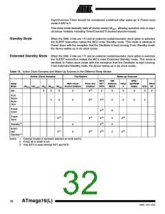
Table 15. Reset Characteristics
Symbol Parameter
Condition
Min
Typ
Max
Units
Power-on Reset
Threshold Voltage (rising)
1.4
2.3
V
VPOT
Power-on Reset
Threshold Voltage
1.3
2.3
V
(falling)(1)
RESET Pin Threshold
Voltage
VRST
0.2 VCC
0.85VCC
V
Minimum pulse width on
RESET Pin
tRST
50
ns
Brown-out Reset
BODLEVEL = 1
BODLEVEL = 0
BODLEVEL = 1
2.5
3.7
2.7
4.0
2
3.2
4.2
Threshold Voltage(2)
VBOT
V
Minimum low voltage
period for Brown-out
Detection
µs
µs
tBOD
BODLEVEL = 0
2
Brown-out Detector
hysteresis
VHYST
50
mV
Notes: 1. The Power-on Reset will not work unless the supply voltage has been below VPOT
(falling).
2. VBOT may be below nominal minimum operating voltage for some devices. For
devices where this is the case, the device is tested down to VCC = VBOT during the
production test. This guarantees that a Brown-out Reset will occur before VCC drops
to a voltage where correct operation of the microcontroller is no longer guaranteed.
The test is performed using BODLEVEL = 1 for ATmega16L and BODLEVEL = 0 for
ATmega16. BODLEVEL = 1 is not applicable for ATmega16.
35
2466E–AVR–10/02

 ATMEL [ ATMEL ]