ATmega16(L)
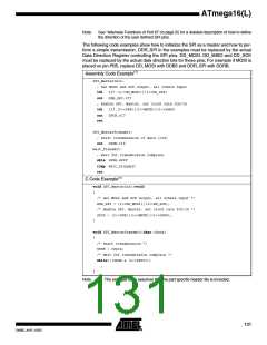
Timer/Counter Interrupt Flag
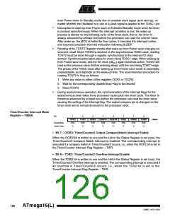
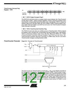
Register – TIFR
Bit
7
OCF2
R/W
0
6
TOV2
R/W
0
5
4
OCF1A
R/W
0
3
OCF1B
R/W
0
2
TOV1
R/W
0
1
OCF0
R/W
0
0
TOV0
R/W
0
ICF1
R/W
0
TIFR
Read/Write
Initial Value
• Bit 7 – OCF2: Output Compare Flag 2
The OCF2 bit is set (one) when a compare match occurs between the Timer/Counter2
and the data in OCR2 – Output Compare Register2. OCF2 is cleared by hardware when
executing the corresponding interrupt handling vector. Alternatively, OCF2 is cleared by
writing a logic one to the flag. When the I-bit in SREG, OCIE2 (Timer/Counter2 Com-
pare match Interrupt Enable), and OCF2 are set (one), the Timer/Counter2 Compare
match Interrupt is executed.
• Bit 6 – TOV2: Timer/Counter2 Overflow Flag
The TOV2 bit is set (one) when an overflow occurs in Timer/Counter2. TOV2 is cleared
by hardware when executing the corresponding interrupt handling vector. Alternatively,
TOV2 is cleared by writing a logic one to the flag. When the SREG I-bit, TOIE2
(Timer/Counter2 Overflow Interrupt Enable), and TOV2 are set (one), the
Timer/Counter2 Overflow interrupt is executed. In PWM mode, this bit is set when
Timer/Counter2 changes counting direction at $00.
Timer/Counter Prescaler Figure 64. Prescaler for Timer/Counter2
clkI/O
clkT2S
10-BIT T/C PRESCALER
Clear
TOSC1
AS2
PSR2
0
CS20
CS21
CS22
TIMER/COUNTER2 CLOCK SOURCE
clkT2
The clock source for Timer/Counter2 is named clkT2S. clkT2S is by default connected to
the main system I/O clock clkIO. By setting the AS2 bit in ASSR, Timer/Counter2 is asyn-
chronously clocked from the TOSC1 pin. This enables use of Timer/Counter2 as a Real
Time Counter (RTC). When AS2 is set, pins TOSC1 and TOSC2 are disconnected from
Port C. A crystal can then be connected between the TOSC1 and TOSC2 pins to serve
as an independent clock source for Timer/Counter2. The Oscillator is optimized for use
with a 32.768 kHz crystal. Applying an external clock source to TOSC1 is not
recommended.
127
2466E–AVR–10/02

 ATMEL [ ATMEL ]