A FOC1A/FOC1B strobe will not generate any interrupt nor will it clear the timer in Clear
Timer on Compare match (CTC) mode using OCR1A as TOP.
The FOC1A/FOC1B bits are always read as zero.
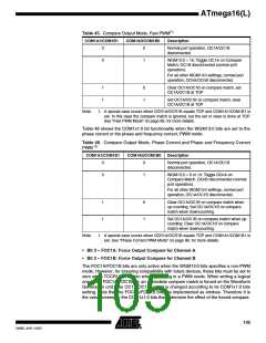
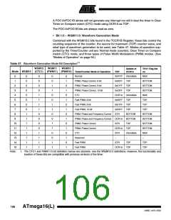
• Bit 1:0 – WGM11:0: Waveform Generation Mode
Combined with the WGM13:2 bits found in the TCCR1B Register, these bits control the
counting sequence of the counter, the source for maximum (TOP) counter value, and
what type of waveform generation to be used, see Table 47. Modes of operation sup-
ported by the Timer/Counter unit are: Normal mode (counter), Clear Timer on Compare
match (CTC) mode, and three types of Pulse Width Modulation (PWM) modes. (See
“Modes of Operation” on page 94.)
Table 47. Waveform Generation Mode Bit Description(1)
WGM12
(CTC1)
WGM11
(PWM11) (PWM10)
WGM10
Update of
OCR1x
TOV1 Flag Set
on
Mode WGM13
Timer/Counter Mode of Operation
Normal
TOP
0xFFFF
0x00FF
0x01FF
0x03FF
OCR1A
0x00FF
0x01FF
0x03FF
ICR1
Immediate
TOP
MAX
0
1
0
0
0
0
0
0
0
0
1
1
1
1
1
1
1
1
0
0
0
0
1
1
1
1
0
0
0
0
1
1
1
1
0
0
1
1
0
0
1
1
0
0
1
1
0
0
1
1
0
1
0
1
0
1
0
1
0
1
0
1
0
1
0
1
PWM, Phase Correct, 8-bit
PWM, Phase Correct, 9-bit
PWM, Phase Correct, 10-bit
CTC
BOTTOM
BOTTOM
BOTTOM
MAX
2
TOP
TOP
3
4
Immediate
TOP
5
Fast PWM, 8-bit
TOP
Fast PWM, 9-bit
TOP
TOP
6
7
Fast PWM, 10-bit
TOP
TOP
8
PWM, Phase and Frequency Correct
PWM, Phase and Frequency Correct
PWM, Phase Correct
PWM, Phase Correct
CTC
BOTTOM
BOTTOM
TOP
BOTTOM
BOTTOM
BOTTOM
BOTTOM
MAX
OCR1A
ICR1
9
10
11
12
13
14
OCR1A
ICR1
TOP
Immediate
–
Reserved
–
–
Fast PWM
ICR1
TOP
TOP
Fast PWM
OCR1A
TOP
TOP
15
Note:
1. The CTC1 and PWM11:0 bit definition names are obsolete. Use the WGM12:0 definitions. However, the functionality and
location of these bits are compatible with previous versions of the timer.
106
ATmega16(L)
2466E–AVR–10/02

 ATMEL [ ATMEL ]