12.4 Register Description for I/O-Ports
12.4.1
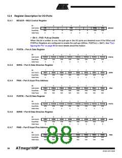
MCUCR – MCU Control Register
Bit
7
6
-
5
-
4
3
–
2
–
1
IVSEL
R/W
0
0
IVCE
R/W
0
0x35 (0x55)
Read/Write
Initial Value
JTD
R/W
0
PUD
R/W
0
MCUCR
R
0
R
0
R
0
R
0
• Bit 4 – PUD: Pull-up Disable
When this bit is written to one, the pull-ups in the I/O ports are disabled even if the DDxn and
PORTxn Registers are configured to enable the pull-ups ({DDxn, PORTxn} = 0b01). See ”Con-
figuring the Pin” on page 66 for more details about this feature.
12.4.2
12.4.3
12.4.4
12.4.5
12.4.6
12.4.7
PORTA – Port A Data Register
Bit
7
6
PORTA6
R/W
0
5
PORTA5
R/W
0
4
PORTA4
R/W
0
3
PORTA3
R/W
0
2
PORTA2
R/W
0
1
PORTA1
R/W
0
0
PORTA0
R/W
0
PORTA7
R/W
0
0x02 (0x22)
Read/Write
Initial Value
PORTA
DDRA
PINA
DDRA – Port A Data Direction Register
Bit
7
DDA7
R/W
0
6
DDA6
R/W
0
5
DDA5
R/W
0
4
DDA4
R/W
0
3
DDA3
R/W
0
2
DDA2
R/W
0
1
DDA1
R/W
0
0
DDA0
R/W
0
0x01 (0x21)
Read/Write
Initial Value
PINA – Port A Input Pins Address
Bit
7
6
5
4
3
2
1
0
0x00 (0x20)
Read/Write
Initial Value
PINA7
R/W
N/A
PINA6
R/W
N/A
PINA5
R/W
N/A
PINA4
R/W
N/A
PINA3
R/W
N/A
PINA2
R/W
N/A
PINA1
R/W
N/A
PINA0
R/W
N/A
PORTB – Port B Data Register
Bit
7
6
PORTB6
R/W
0
5
PORTB5
R/W
0
4
PORTB4
R/W
0
3
PORTB3
R/W
0
2
PORTB2
R/W
0
1
PORTB1
R/W
0
0
PORTB0
R/W
0
PORTB7
R/W
0
PORTB
DDRB
PINB
0x05 (0x25)
Read/Write
Initial Value
DDRB – Port B Data Direction Register
Bit
7
DDB7
R/W
0
6
DDB6
R/W
0
5
DDB5
R/W
0
4
DDB4
R/W
0
3
DDB3
R/W
0
2
DDB2
R/W
0
1
DDB1
R/W
0
0
DDB0
R/W
0
0x04 (0x24)
Read/Write
Initial Value
PINB – Port B Input Pins Address
Bit
7
6
5
4
3
2
1
0
0x03 (0x23)
Read/Write
Initial Value
PINB7
R/W
N/A
PINB6
R/W
N/A
PINB5
R/W
N/A
PINB4
R/W
N/A
PINB3
R/W
N/A
PINB2
R/W
N/A
PINB1
R/W
N/A
PINB0
R/W
N/A
88
ATmega169P
8018A–AVR–03/06

 ATMEL [ ATMEL ]