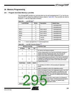
Table 26-2. Lock Bit Protection Modes(1)(2) (Continued)
Memory Lock Bits
Protection Type
No restrictions for SPM or LPM accessing the Boot Loader
section.
1
2
1
1
1
0
SPM is not allowed to write to the Boot Loader section.
SPM is not allowed to write to the Boot Loader section, and LPM
executing from the Application section is not allowed to read
from the Boot Loader section. If Interrupt Vectors are placed in
the Application section, interrupts are disabled while executing
from the Boot Loader section.
3
0
0
LPM executing from the Application section is not allowed to
read from the Boot Loader section. If Interrupt Vectors are
placed in the Application section, interrupts are disabled while
executing from the Boot Loader section.
4
0
1
Notes: 1. Program the Fuse bits and Boot Lock bits before programming the LB1 and LB2.
2. “1” means unprogrammed, “0” means programmed
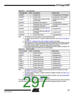
26.2 Fuse Bits
The ATmega169P has three Fuse bytes. Table 26-3 - Table 26-5 describe briefly the functional-
ity of all the fuses and how they are mapped into the Fuse bytes. Note that the fuses are read as
logical zero, “0”, if they are programmed.
Table 26-3. Extended Fuse Byte
Fuse Low Byte
Bit No
Description
Default Value
–
7
6
5
4
3
2
1
0
–
1
–
–
1
–
–
1
–
–
1
BODLEVEL2(1)
BODLEVEL1(1)
BODLEVEL0(1)
RSTDISBL(2)
Brown-out Detector trigger level
Brown-out Detector trigger level
Brown-out Detector trigger level
External Reset Disable
1 (unprogrammed)
1 (unprogrammed)
1 (unprogrammed)
1 (unprogrammed)
Notes: 1. See Table 9-2 on page 49 for BODLEVEL Fuse decoding.
2. Port G, PG5 is input only. Pull-up is always on. See ”Alternate Functions of Port G” on page
85.
296
ATmega169P
8018A–AVR–03/06

 ATMEL [ ATMEL ]