ATmega640/1280/1281/2560/2561
12.5 Register Description
12.5.1
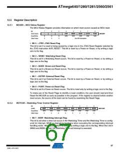
MCUSR – MCU Status Register
The MCU Status Register provides information on which reset source caused an MCU reset.
Bit
7
–
6
–
5
–
4
3
2
1
0
0x35 (0x55)
Read/Write
Initial Value
JTRF
R/W
WDRF
R/W
BORF
R/W
EXTRF
R/W
PORF
R/W
MCUSR
R
0
R
0
R
0
See Bit Description
• Bit 4 – JTRF: JTAG Reset Flag
This bit is set if a reset is being caused by a logic one in the JTAG Reset Register selected by
the JTAG instruction AVR_RESET. This bit is reset by a Power-on Reset, or by writing a logic
zero to the flag.
• Bit 3 – WDRF: Watchdog Reset Flag
This bit is set if a Watchdog Reset occurs. The bit is reset by a Power-on Reset, or by writing a
logic zero to the flag.
• Bit 2 – BORF: Brown-out Reset Flag
This bit is set if a Brown-out Reset occurs. The bit is reset by a Power-on Reset, or by writing a
logic zero to the flag.
• Bit 1 – EXTRF: External Reset Flag
This bit is set if an External Reset occurs. The bit is reset by a Power-on Reset, or by writing a
logic zero to the flag.
• Bit 0 – PORF: Power-on Reset Flag
This bit is set if a Power-on Reset occurs. The bit is reset only by writing a logic zero to the flag.
To make use of the Reset Flags to identify a reset condition, the user should read and then
Reset the MCUSR as early as possible in the program. If the register is cleared before another
reset occurs, the source of the reset can be found by examining the Reset Flags.
12.5.2
WDTCSR – Watchdog Timer Control Register
Bit
(0x60)
7
6
5
4
WDCE
R/W
0
3
2
WDP2
R/W
0
1
WDP1
R/W
0
0
WDP0
R/W
0
WDIF
WDIE
WDP3
R/W
0
WDE
R/W
X
WDTCSR
Read/Write
R/W
R/W
Initial Value
0
0
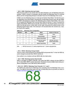
• Bit 7 - WDIF: Watchdog Interrupt Flag
This bit is set when a time-out occurs in the Watchdog Timer and the Watchdog Timer is config-
ured for interrupt. WDIF is cleared by hardware when executing the corresponding interrupt
handling vector. Alternatively, WDIF is cleared by writing a logic one to the flag. When the I-bit in
SREG and WDIE are set, the Watchdog Time-out Interrupt is executed.
67
2549L–AVR–08/07

 ATMEL [ ATMEL ]