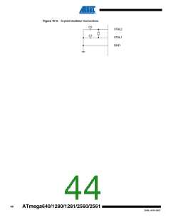
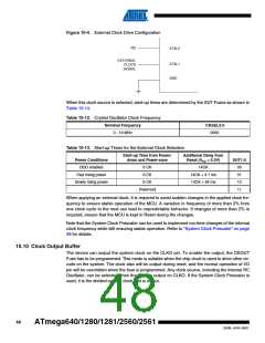
Figure 10-4. External Clock Drive Configuration
NC
XTAL2
EXTERNAL
CLOCK
XTAL1
GND
SIGNAL
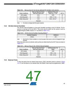
When this clock source is selected, start-up times are determined by the SUT Fuses as shown in
Table 10-14.
Table 10-12. Crystal Oscillator Clock Frequency
Nominal Frequency
CKSEL3:0
0 - 16 MHz
0000
Table 10-13. Start-up Times for the External Clock Selection
Start-up Time from Power-
down and Power-save
Additional Delay from
Reset (VCC = 5.0V)
Power Conditions
BOD enabled
SUT1:0
00
6 CK
6 CK
14CK
Fast rising power
Slowly rising power
14CK + 4.1 ms
14CK + 65 ms
01
6 CK
10
Reserved
11
When applying an external clock, it is required to avoid sudden changes in the applied clock fre-
quency to ensure stable operation of the MCU. A variation in frequency of more than 2% from
one clock cycle to the next can lead to unpredictable behavior. If changes of more than 2% is
required, ensure that the MCU is kept in Reset during the changes.
Note that the System Clock Prescaler can be used to implement run-time changes of the internal
clock frequency while still ensuring stable operation. Refer to “System Clock Prescaler” on page
49 for details.
10.10 Clock Output Buffer
The device can output the system clock on the CLKO pin. To enable the output, the CKOUT
Fuse has to be programmed. This mode is suitable when the chip clock is used to drive other cir-
cuits on the system. The clock also will be output during reset, and the normal operation of I/O
pin will be overridden when the fuse is programmed. Any clock source, including the internal RC
Oscillator, can be selected when the clock is output on CLKO. If the System Clock Prescaler is
used, it is the divided system clock that is output.
48
ATmega640/1280/1281/2560/2561
2549L–AVR–08/07

 ATMEL [ ATMEL ]