ATmega640/1280/1281/2560/2561
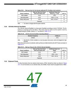
Table 10-9. Start-up times for the internal calibrated RC Oscillator clock selection
Start-up Time from Power-
down and Power-save
Additional Delay from
Reset (VCC = 5.0V)
Power Conditions
BOD enabled
SUT1:0
00
6 CK
6 CK
14CK
Fast rising power
Slowly rising power
14CK + 4.1 ms
14CK + 65 ms(1)
01
6 CK
10
Reserved
11
Note:
1. The device is shipped with this option selected.
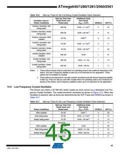
10.8 128 kHz Internal Oscillator
The 128 kHz internal Oscillator is a low power Oscillator providing a clock of 128 kHz. The fre-
quency is nominal at 3V and 25°C. This clock may be select as the system clock by
programming the CKSEL Fuses to “11” as shown in Table 10-10.
Table 10-10. 128 kHz Internal Oscillator Operating Modes(1)
Nominal Frequency
CKSEL3:0
128 kHz
0011
Note:
1. Note that the 128 kHz oscillator is a very low power clock source, and is not designed for high
accuracy.
When this clock source is selected, start-up times are determined by the SUT Fuses as shown in
Table 10-11.
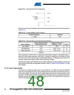
Table 10-11. Start-up Times for the 128 kHz Internal Oscillator
Start-up Time from Power-
down and Power-save
Additional Delay from
Reset
Power Conditions
BOD enabled
SUT1:0
00
6 CK
6 CK
14CK
Fast rising power
Slowly rising power
14CK + 4 ms
14CK + 64 ms
01
6 CK
10
Reserved
11
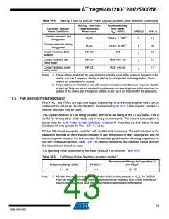
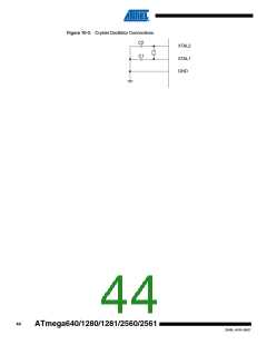
10.9 External Clock
To drive the device from an external clock source, XTAL1 should be driven as shown in Figure
10-4. To run the device on an external clock, the CKSEL Fuses must be programmed to “0000”.
47
2549L–AVR–08/07

 ATMEL [ ATMEL ]