AT90PWM2/3/2B/3B
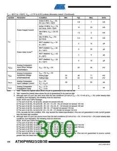
5. Minimum VCC for Power-down is 2.5V.
6. The Analog Comparator Propogation Delay equals 1 comparator clock plus 30 nS. See “Analog Comparator” on page 226.
for comparator clock definition.
26.3 External Clock Drive Characteristics
26.3.1
Calibrated Internal RC Oscillator Accuracy
Table 26-1. Calibration Accuracy of Internal RC Oscillator
Frequency
VCC
Temperature
Calibration Accuracy
Factory
Calibration
8.0 MHz
3V
25°C
10%
User
Calibration
7.3 - 8.1 MHz
2.7V - 5.5V
-40°C - 85°C
1%
26.3.2
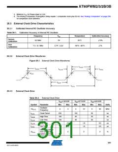
External Clock Drive Waveforms
Figure 26-1. External Clock Drive Waveforms
VIH1
VIL1
26.3.3
External Clock Drive
Table 26-2. External Clock Drive
VCC=1.8-5.5V
VCC=2.7-5.5V
VCC=4.5-5.5V
Symbol
Parameter
Min.
Max.
Min.
Max.
Min.
Max.
Units
Oscillator
Frequency
1/tCLCL
0
4
0
10
0
20
MHz
tCLCL
tCHCX
tCLCX
tCLCH
tCHCL
Clock Period
High Time
Low Time
Rise Time
Fall Time
250
100
100
100
40
50
20
20
ns
ns
ns
μs
μs
40
2.0
2.0
1.6
1.6
0.5
0.5
Change in period
from one clock
cycle to the next
ΔtCLCL
2
2
2
%
301
4317J–AVR–08/10

 ATMEL [ ATMEL ]