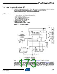
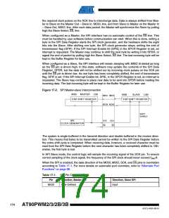
AT90PWM2/3/2B/3B
TABLE 2.
Assembly Code Example(1)
SPI_SlaveInit:
; Set MISO output, all others input
ldi r17,(1<<DD_MISO)
out DDR_SPI,r17
; Enable SPI
ldi r17,(1<<SPE)
out SPCR,r17
ret
SPI_SlaveReceive:
; Wait for reception complete
sbis SPSR,SPIF
rjmp SPI_SlaveReceive
; Read received data and return
in
r16,SPDR
ret
C Code Example(1)
void SPI_SlaveInit(void)
{
/* Set MISO output, all others input */
DDR_SPI = (1<<DD_MISO);
/* Enable SPI */
SPCR = (1<<SPE);
}
char SPI_SlaveReceive(void)
{
/* Wait for reception complete */
while(!(SPSR & (1<<SPIF)))
;
/* Return data register */
return SPDR;
}
Note:
1. The example code assumes that the part specific header file is included.
17.2 SS Pin Functionality
17.2.1
Slave Mode
When the SPI is configured as a Slave, the Slave Select (SS) pin is always input. When SS is
held low, the SPI is activated, and MISO becomes an output if configured so by the user. All
other pins are inputs. When SS is driven high, all pins are inputs, and the SPI is passive, which
177
4317J–AVR–08/10

 ATMEL [ ATMEL ]