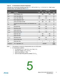
Table 5-3. AC Characteristics (Industrial Temperature)
Applicable over recommended operating range from: TAI = −40°C to +85°C, VCC = 1.7V to 5.5V, CL = 100pF (unless
otherwise noted). Test conditions are listed in Note 2.
1.7V
2.5V, 5.0V
Symbol
fSCL
Parameter
Min
Max
Min
Max
Units
kHz
ns
Clock Frequency, SCL
Clock Pulse Width Low
Clock Pulse Width High
Noise Suppression Time(1)
Clock Low to Data Out Valid
400
1000
tLOW
tHIGH
tI
1300
600
400
400
ns
100
900
50
ns
tAA
50
50
550
ns
Time the bus must be free before a new transmission can
start(1)
tBUF
1300
500
ns
tHD.STA
tSU.STA
tHD.DAT
tSU.DAT
tR
Start Hold Time
600
600
0
250
250
0
ns
ns
ns
ns
ns
ns
ns
ns
ms
Start Set-up Time
Data In Hold Time
Data In Set-up Time
Inputs Rise Time(1)
Inputs Fall Time(1)
Stop Set-up Time
Data Out Hold Time
Write Cycle Time
100
100
300
300
300
100
tF
tSU.STO
tDH
600
50
250
50
tWR
5
5
Write
Cycles
Endurance(1) 25°C, Page Mode, 3.3V
1,000,000
Notes: 1. This parameter is ensured by characterization and is not 100% tested.
2. AC measurement conditions:
RL (connects to VCC): 1.3kΩ (2.5V, 5.5V), 10kΩ (1.7V)
Input pulse voltages: 0.3VCC to 0.7VCC
Input rise and fall times: ≤ 50ns
Input and output timing reference voltages: 0.5 x VCC
Atmel AT24C128C [DATASHEET]
5
8734B–SEEPR–9/2012

 ATMEL [ ATMEL ]