5.
Memory Organization
Atmel AT24C128C, 128K Serial EEPROM: The 128K is internally organized as 256 pages of 64-bytes each. Random
word addressing requires a 14-bit data word address.
Table 5-1. Pin Capacitance(1)
Applicable over recommended operating range from: TA = 25°C, f = 1.0MHz, VCC = 1.7V to 5.5V.
Symbol
CI/O
Test Condition
Max
8
Units
pF
Conditions
VI/O = 0V
VIN = 0V
Input/Output Capacitance (SDA)
Input Capacitance (A0, A1, A2, and SCL)
CIN
6
pF
Note: 1. This parameter is characterized and is not 100% tested.
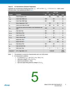
Table 5-2. DC Characteristics
Applicable over recommended operating range from: TAI = -40°C to +85°C, VCC = 1.7V to 5.5V (unless otherwise noted).
Symbol
VCC1
ICC1
Parameter
Test Condition
Min
Typ
Max
5.5
2.0
3.0
1.0
6.0
Units
V
Supply Voltage
Supply Current
Supply Current
1.7
VCC = 5.0V
VCC = 5.0V
VCC = 1.7V
VCC = 5.0V
Read at 400kHz
Write at 400kHz
1.0
2.0
mA
mA
A
ICC2
ISB1
Standby Current
VIN = VCC or VSS
A
Input Leakage
ILI
VIN = VCC or VSS
0.10
0.05
3.0
3.0
A
A
Current VCC = 5.0V
Output Leakage
ILO
VOUT = VCC or VSS
Current VCC = 5.0V
VIL
Input Low Level(1)
Input High Level((1)
Output Low Level
Output Low Level
-0.6
VCC x 0.3
VCC + 0.5
0.2
V
V
V
V
VIH
VCC x 0.7
VOL1
VOL2
VCC = 1.7V
VCC = 3.0V
IOL = 0.15mA
IOL = 2.1mA
0.4
Note: 1. VIL min and VIH max are reference only and are not tested.
Atmel AT24C128C [DATASHEET]
4
8734B–SEEPR–9/2012

 ATMEL [ ATMEL ]