AT89C5132
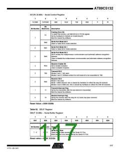
SCON (S:98h) – Serial Control Register
7
6
5
4
3
2
1
0
FE/SM0
OVR/SM1
SM2
REN
TB8
RB8
TI
RI
Bit
Bit Number Mnemonic Description
Framing Error Bit
To select this function, set SMOD0 bit in PCON register.
Set by hardware to indicate an invalid stop bit.
Must be cleared by software.
FE
7
Serial Port Mode Bit 0
SM0
SM1
Refer to Table 89 for mode selection.
Serial Port Mode Bit 1
Refer to Table 89 for mode selection.
6
5
Serial Port Mode Bit 2
Set to enable the multiprocessor communication and automatic address recognition
SM2
features.
Clear to disable the multiprocessor communication and automatic address recognition
features.
Receiver Enable Bit
4
3
REN
TB8
Set to enable reception.
Clear to disable reception.
Transmit Bit 8
Modes 0 and 1: Not used.
Modes 2 and 3: Software writes the ninth data bit to be transmitted to TB8.
Receiver Bit 8
Mode 0: Not used.
2
RB8
Mode 1 (SM2 cleared): Set or cleared by hardware to reflect the stop bit received.
Modes 2 and 3 (SM2 set): Set or cleared by hardware to reflect the ninth bit received.
Transmit Interrupt Flag
Set by the transmitter after the last data bit is transmitted.
Must be cleared by software.
1
0
TI
Receive Interrupt Flag
RI
Set by the receiver after the stop bit of a frame has been received.
Must be cleared by software.
Reset Value = 0000 0000b
Table 92. SBUF Register
SBUF (S:99h) – Serial Buffer Register
7
6
5
4
3
2
1
0
SD7
SD6
SD5
SD4
SD3
SD2
SD1
SD0
Bit
Bit Number Mnemonic Description
Serial Data Byte
Read the last data received by the Serial I/O Port.
Write the data to be transmitted by the Serial I/O Port.
7 - 0
SD7:0
Reset value = XXXX XXXXb
117
4173E–USB–09/07

 ATMEL [ ATMEL ]