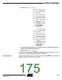
Figure 80. Nand Flash Read Example
manual
return in
read mode
dum
my
dum
my
ACT
OK
ACT
End of
page
CMD NFD NFD CMDADC ADR ADR CED ADR CMD NFD NFD NFD NFD NFD NFD NFD CMD CED ACT
ifc CPU Dev
70h ATF ATF 00h
C
R1 R2 =0 R3 70h ATF ATF ATF ATF ATF ATF ATF 00h =1 (R)
OK
CED
Ready
RE
Must be held low during Tr
Tr
Data zone
Spare zone
(Check ECC; etc...)
BUSYD
auto
Check
Legend:
•
“ifc CPU” illustrates the commands given by the CPU to the NFC.
“auto” illustrates the actions automatically launched by the NFC.
•
•
•
•
“ready” is the flow control line between the DFC macro and the NFC interface.
“BUSYD” is the busy state of the device D.
“P” is the Polling action.
Data Unit
The Data Unit works closely to the DFC and is responsible of all the data transfer
between the NF memories and on-chip memories (USB, SRAM, …).
Data and Spare Zone
For management convenience, the controller is mapping a memory page as some data
and spare zones.
A ‘data zone’ is a data area composed of NDB contiguous bytes.
The ‘spare zone’ is located after the ‘data zone’ until the end of the page.
NDB is part of the configuration descriptor (see Table 189) and its use is described in
the following examples:
•
SMC page, “512B” NF page, “512B” XD card
A page is composed of 512 contiguous data bytes (NDB= 1), followed by a spare
zone of 16 bytes.
Spare
zone
Data zone
512 B
16 B
•
“2kB” NF page
A page is composed of 1024 contiguous data bytes (NDB= 4), followed by a spare
zone of 64 bytes.
Spare
zone
Data zone
2048 B
64 B
Spare Zone Content
The “16-byte” spare zone contains information as specified in Table 195.
176
AT85C51SND3Bx
7632A–MP3–03/06

 ATMEL [ ATMEL ]