AT8xC51SND2C
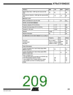
AC Characteristics
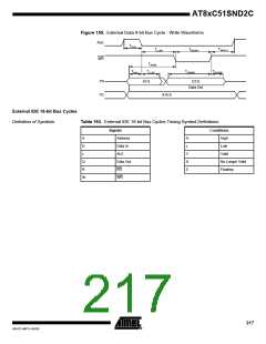
External Program Bus Cycles
Definition of Symbols
Table 188. External Program Bus Cycles Timing Symbol Definitions
Signals
Address
Conditions
High
A
I
H
L
Instruction In
ALE
Low
L
P
V
X
Z
Valid
PSEN
No Longer Valid
Floating
Timings
Test conditions: capacitive load on all pins= 50 pF.
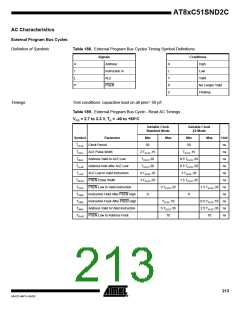
Table 189. External Program Bus Cycle - Read AC Timings
DD = 2.7 to 3.3 V, TA = -40 to +85°C
V
Variable Clock
Standard Mode
Variable Clock
X2 Mode
Symbol
Parameter
Min
Max
Min
Max
Unit
ns
TCLCL Clock Period
50
50
TLHLL ALE Pulse Width
2·TCLCL-15
TCLCL-20
TCLCL-20
4·TCLCL-35
3·TCLCL-25
TCLCL-15
ns
TAVLL
Address Valid to ALE Low
0.5·TCLCL-20
0.5·TCLCL-20
2·TCLCL-35
1.5·TCLCL-25
ns
TLLAX Address hold after ALE Low
ns
TLLIV
TPLPH PSEN Pulse Width
ALE Low to Valid Instruction
ns
ns
TPLIV
TPXIX
TPXIZ
TAVIV
PSEN Low to Valid Instruction
3·TCLCL-35
1.5·TCLCL-35 ns
ns
Instruction Hold After PSEN High
Instruction Float After PSEN High
Address Valid to Valid Instruction
0
0
TCLCL-10
5·TCLCL-35
10
0.5·TCLCL-10 ns
2.5·TCLCL-35 ns
TPLAZ PSEN Low to Address Float
10
ns
213
4341D–MP3–04/05

 ATMEL [ ATMEL ]