AX88179
USB 3.0 to 10/100/1000M Gigabit Ethernet Controller
4.1 Detailed Description
The following sections provide detailed descriptions for some of the fields in memory maps of serial EEPROM and eFuse.
Please refer to AX88179 EEPROM User Guide for more details.
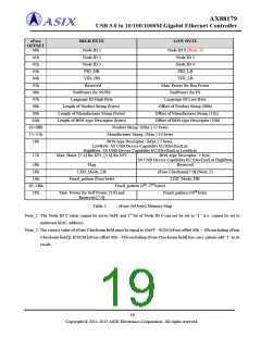
4.1.1 Node ID (00~02h)
The Node ID 0 to 5 bytes represent the MAC address of the device, for example, if MAC address = 04-23-45-67-89-AB,
then Node ID 0 = 04h, Node ID 1 = 23h, Node ID 2 = 45h, Node ID 3 = 67h, Node ID 4 = 89h, and Node ID 5 = ABh.
Default values: Node ID {0, 1, 2, 3, 4, 5} = 00-0E-C6-81-79-01.
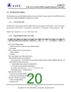
4.1.2 Flag (EEPROM: 05h, eFuse:18h)
Bit 7
Bit 6
Bit 5
Bit 4
PME_PIN
Bit 3
SNT
Bit 2
0
Bit 1
WOLLP
Bit 0
RWU
PME_IND PME_TYPE PME_POL
RWU: Remote Wakeup support.
1: Indicate that this device supports Remote Wakeup (default).
0: Not support.
WOLLP: Wake-On-LAN Low Power function.
1: Enabled (default).
0: Disabled.
SNT: Serial Number Type. (Only valid for eFuse)
When SEEPROM loader selected EEPROM:
Please set this bit to ‘0’ for EEPROM. The Serial Number String will refer to Table 4 EEPROM offset 26h ~2Ch.
When SEEPROM loader selected eFuse:
1: Serial Number String is fixed to “00000000000001”.
0: Use Node ID as Serial Number String (default).
For example, when Node ID {0, 1, 2, 3, 4, 5} = 00-0E-C6-81-79-01,
Serial Number String = “00000EC6817901”.
PME_PIN: PME / GPIO_0.
1: Set GPIO_0 pin as PME (default).
0: GPIO_0 pin is controlled by vendor command.
PME_POL: PME pin active Polarity.
1: PME active high (default).
0: PME active low.
19
Copyright © 2011-2012 ASIX Electronics Corporation. All rights reserved.

 ASIX [ ASIX ELECTRONICS CORPORATION ]