APW7302B
Application Information(Cont.)
Output Capacitor Selection (Cont.)
VOUT ·(VIN - VOUT)
340000·L·VIN
£ 1.2
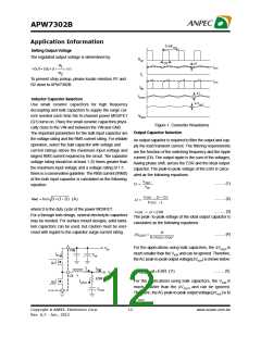
The load transient requirements are the function of the
slew rate (di/dt) and the magnitude of the transient load
urrent. These requirements are generally met with a
mix of capacitors and careful layout. High frequency ca-
pacitors initially supply the transient and slow the current
load rate seen by the bulk capacitors. The bulk filter ca-
pacitor values are generally determined by the ESR
(Effective Series Resistance) and voltage rating require-
ments rather than actual capacitance requirements.
High frequency decoupling capacitors should be placed
as close to the power pins of the load as physically
possible. Be careful not to add inductance in the circuit
board wiring that could cancel the usefulness of these
low inductance components. An aluminum electrolytic
capacitor’s ESR value is related to the case size with lower
ESR available in larger case sizes. However, the Equiva-
lent Series Inductance (ESL) of these capacitors increases
with case size and can reduce the usefulness of the ca-
pacitor to high slew-rate transient loading.
VOUT ·(VIN - VOUT)
408000 ·VIN
L ³
(H)
........... (6)
where V = V
IN
IN(MAX)
Table2 Inductor Selection Guide
Inductance DCR
Current
Rating(A)
Vender
Model
(mH)
(mW)
CYNTEC PCMB063T-100MS
Gausstek PL94P051M-15U
Gausstek PL94P051M-10U
10
62
4
3
15
10
50
38
3.8
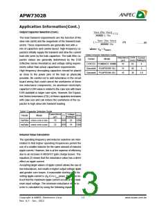
Table1 Capacitor Selection Guide
Capacitance
Voltage
Rating(V)
Vender
Model
TC
Si2e
(mF)
GRM31CR61E106K
GRM31CR61C226K
muRata
muRata
10
22
X5R
X5R
25
16
1206
1206
Inductor Value Calculation
The operating frequency and inductor selection are inter-
related in that higher operating frequencies permit the
use of a smaller inductor for the same amount of inductor
ripple current. However, this is at the expense of efficiency
due to an increase in MOSFET gate charge losses. The
equation (2) shows that the inductance value has a direct
effect on ripple current.
Accepting larger values of ripple current allows the use of
low inductances, but results in higher output voltage ripple
and greater core losses. A reasonable starting point for
setting ripple current is DI< 0.4 x IOUT(max). Please be no-
ticed that the maximum ripple current occurs at the maxi-
mum input voltage. The minimum inductance of the in-
uctor is calculated by using the following equation:
Copyright ã ANPEC Electronics Corp.
13
www.anpec.com.tw
Rev. A.2 - Jan., 2012

 ANPEC [ ANPEC ELECTRONICS COROPRATION ]