APA2069
Application Descriptions (Cont.)
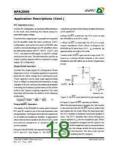
Volume Control Function
Input Resistance, Ri
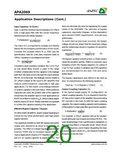
APA2069 hasan internal stereo volume control whose The gain for each audio input of theAPA2069 isset by
setting is a function of the DC voltage applied to the the internal resistors (Ri and Rf) of volume control
VOLUMEinput pin.TheAPA2069volumecontrol con- amplifier ininverting configuration.
RF
Ri
RF
Ri
sists of 32 steps that are individually selected by a
variableDCvoltage level on theVOLUME control pin.
The range of the steps, controlled by theDC voltage,
are from 20dB to -80dB. Each gain step corresponds
to a specific input voltage range, as shown in table.
To minimize the effect of noise on the volume control
pin, which can affect the selected gain level, hyster-
esis and clock delay are implemented. The amount of
hysteresis corresponds to half of the step width, as
shown in volume control graph.
-
=
AV
(2)
(3)
SE Gain =
-2 x
=
BTLGain
BTL mode operation brings the factor of 2 in the gain
equation due to the inverting amplifier mirroring the
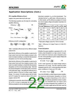
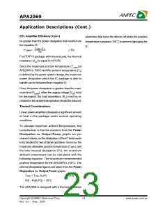
voltage swing across the load. For the varying gain
setting, APA2069 generates each input resistance on
figure4.Theinputresistancewillaffectthelowfrequency
performance of audio signal. The minmum input
resistance is 10kW when gain setting is 20dB and the
resistance will ramp up when close loop gain below
20dB.The input resistance haswidevariation(+/-10%)
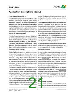
APA2069DCVolumeControlCurve(BTL)
20
caused by process variation.
Ri vs Gain(BTL)
10
0
Ri(k )
W
120
Forward
-10
100
80
-20
Backward
-30
-40
-50
-60
-70
-80
60
40
20
0
0.0
0.5
1.0 1.5
2.0
2.5
3.0
3.5
4.0
4.5
5.0
DC volume (V)
-40
-30
-20
-10
0
10
20
Gain(dB)
Figure 3: Gain setting vs VOLUME pin voltage
Figure 4: Input resistance vsGain setting
For highest accuracy, the voltage shown in the ‘rec-
ommended voltage’ column of the table is used to
select a desired gain. This recommended voltage is
exactly halfway between the two nearest transitions.
The gain levels are 2dB/step from 20dB to -40dB in
BTL mode, and the last step at -80dB as mute mode.
Input Capacitor, Ci
In the typical application an input capacitor, Ci, is
required to allow the amplifier to bias the input signal
to the proper DC level for optimum operation. In this
Copyright ã ANPEC Electronics Corp.
19
www.anpec.com.tw
Rev. A.1 - Aug., 2005

 ANPEC [ ANPEC ELECTRONICS COROPRATION ]