APA2069
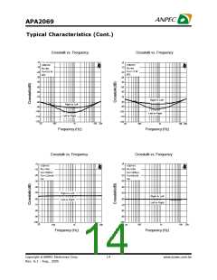
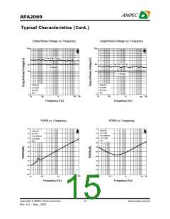
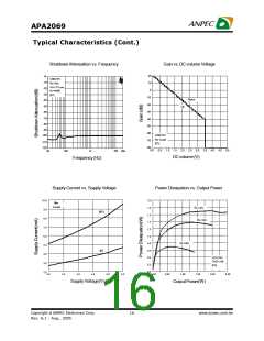
Application Descriptions (Cont.)
BTL Operation (Cont.)
overtheSEconfiguration,asitprovidesdifferentialdrive controlstheoperationofthefolloweramplifierthatdrives
to the load, thus doubling the output swing for LOUT-andROUT-.
aspecified supply voltage.
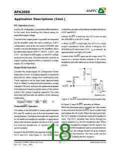
· When SE/BTL is held low, the OP2 is turn on and
Four times the output power is possible as compared the APA2069 is in the BTL mode.
toa SE amplifier under the same conditions. A BTL
· When SE/BTL is held high, the OP2 is in a high
configuration, such as the one used in APA2069, also
output impedance state, which configures the
createsa second advantage over SE amplifiers. Since
APA2069 as SE driver from OUT+. IDD isreduced by
the differential outputs, ROUT+, ROUT-, LOUT+, and
approximately one-half in SE mode.
LOUT-, are biased at half-supply, no needDC voltage
Control of the SE/BTL input can be a logic-level TTL
exists acrossthe load. This eliminates the need for an
source or a resistor divider network or the stereo
output coupling capacitor which is required in a single
headphonejack with switchpin asshown inApplication
supply, SE configuration.
Circuit.
Single-Ended Operation
Consider the single-supply SE configuration shown
1kW
Application Circuit. Acoupling capacitor is required to
VDD
block the DC offset voltage from reaching the load.
These capacitors can be quite large (approximately
33mF to 1000mF) so they tend tobe expensive, occupy
valuable PCB area, and have the additional drawback
of limiting low-frequency performance of the system
(refer to the Output Coupling Capacitor).The rules
described still hold with the addition of the following
relationship:
Control
Pin
Ring
100kW
SE/BTL
Sleeve
Tip
Headphone Jack
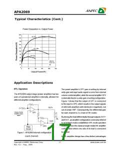
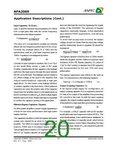
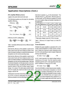
Figure 2: SE/BTL input selection by phonejack plug
1
1
1
£
<<
(1)
Cbypass x 125kW
RiCi
RLCC
In Figure 2, input SE/BTL operates as follows :
When the phonejack plug is inserted, the 1kW resistor
is disconnected and the SE/BTL input is pulled high
and enables the SE mode. When the input goes high,
the OUT- amplifier isshutdown causing the speaker to
mute. The OUT+ amplifier then drives through the
output capacitor (CO) into the headphone jack. When
there is no headphone plugged into the system, the
contact pin of the headphone jack is connnected from
the signal pin, the voltage divider set up by resistors
100kW and 1kW.Resistor 1kW then pulls low the
SE/BTL pin, enabling the BTL function.
Output SE/BTL Operation
The ability of the APA2069 to easily switch between
BTL and SE modes is one of its most important costs
savingfeatures.Thisfeatureeliminatestherequirement
for an additional headphone amplifier in applications
whereinternal stereospeakersare driven inBTLmode
but external headphone or speakers must be
accommodated.
Internal to theAPA2069, two separateamplifiersdrive
OUT+ and OUT- (see Figure 1). The SE/BTL input
Copyright ã ANPEC Electronics Corp.
18
www.anpec.com.tw
Rev. A.1 - Aug., 2005

 ANPEC [ ANPEC ELECTRONICS COROPRATION ]