AS8221
Data Sheet - Detailed Description
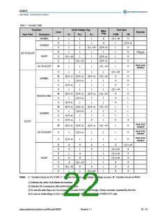
Table 10. Bit order for the read-out sequence
Bit
Description
BM open line
Symbol
BM_OL
BM_VCC
BM_GND
BP_BM
OT
Bit 7
BM short sourced to VCC
BM short sourced to GND
Short circuit between BP and BM
Over temperature
Bit 8
Bit 9
Bit 10
Bit 11
Bit 12
Bit 13
Bit 14
Bit 15
TxEN_BGE timeout
Local wake flag
TxEN_TO
LWAKE
RWAKE
PWON
Remote wake flag
Power on flag
When the read-out mechanism is started, the first data information is the Bit 0 until Bit 15 is transmitted. Any re-initiation or repetitions is started
with the first data Bit 0.
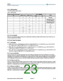
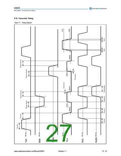
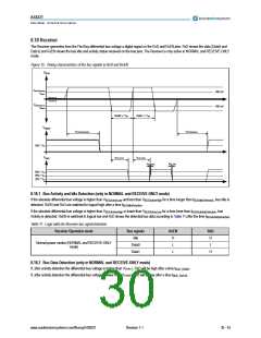
8.15 Bus Driver
8.15.1 Bus States
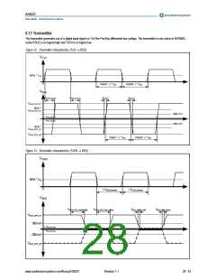
Activity: The bus wires reflects the differential signal specified in chapter 8.17 Transmitter on page 28.
Idle: The bus wires are terminated to VCC/2 via. receiver input resistances.
Idle_LP: The bus wires are terminated to GND via receiver input resistances.
Idle_HZ: The bus wires are not terminated to VCC/2 via. 1MΩ
www.austriamicrosystems.com/flexray/AS8221
Revision 1.1
26 - 43

 AMSCO [ AMS(艾迈斯) ]