AS8221
Data Sheet - Detailed Description
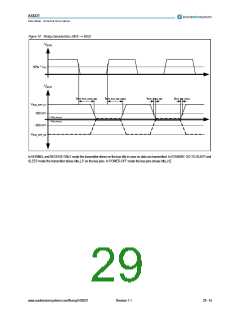
8.18 Receiver
The Receiver generates from the FlexRay differential bus voltage a digital signal on the RxD and RxEN pins. RxD shows the data (Data0 and
Data1) and RxEN shows the bus idle and activity status received on the bus pins. The Receiver is only active in NORMAL and RECEIVE-ONLY
mode.
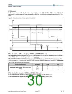
Figure 15. Timing characteristics of the bus signals to RxD and RxEN
VBUS
VBUSActiveHigh
300 mV
VData1
+ VBUS_DIFF_Idle
- VBUS_DIFF_Idle
VBUSActiveLow
- 300 mV
VData0
Data0: x * tBIT
Data1: x * tBIT
VRxEN
tBUSActivityReaction
tBUSIdleReaction
50% * V
IO
tBUS_RxD10
tBUS_RxD01
VRxD
tRxD_FALL
tRxD_RISE
80% * V
50% * V
20% * V
IO
IO
IO
8.18.1 Bus Activity and Idle Detection (only in NORMAL and RECEIVE-ONLY mode)
If the absolute differential bus voltage is higher than VBUSActiveLow and less than VBUSActiveHigh for a time longer than tBUSIdleDetection, bus Idle is
detected, RxEN and RxD are switched to logical high after a time tBUSIdleReaction
.
If the absolute differential bus voltage is higher than VBUSActiveHigh or lower than VBUSActiveLow for a time loner than tBUSActivitiyDetection, bus
Activity is detected, RxEN is switched to logical low and RxD shows the detected bus data according to Table 11 after the time tBUSActivityReaction
.
Table 11. Logic table for Receiver bus signal detection
Receiver Operation mode
Bus signals
Idle
RxEN
RxD
H
H
L
L
Normal power modes (NORMAL and RECEIVE-ONLY
mode)
Data0
L
Data1
H
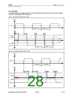
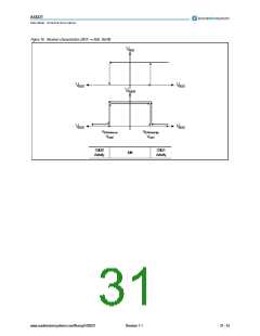
8.18.2 Bus Data Detection (only in NORMAL and RECEIVE-ONLY mode)
If, after activity detection the differential bus voltage is higher than VData1, RxD will be high after a time tBUS_RxD01
.
If, after activity detection the differential bus voltage is lower than VData0, RxD will be low after a time tBUS_RxD10
.
www.austriamicrosystems.com/flexray/AS8221
Revision 1.1
30 - 43

 AMSCO [ AMS(艾迈斯) ]