AS8221
Data Sheet - Detailed Description
8.13.3 Power on Flag (PWON)
The PWON is set leaving the POWER-OFF state and it is reset entering a low-power mode after a non-low-power mode.
8.14 Error Flags and Status Flags Read-Out
The readout mechanism consists of two information groups:
5. Error read-out
6. Status information read-out
The read-out mechanism as serial transmission on Pin EN and ERRN:
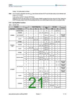
Table 9. Read-out Mechanism and Transceiver States
State
Enabled/Disabled
Enabled
NORMAL mode
RECEIVE-ONLY mode
STANDBY mode
GO-TO-SLEEP mode
SLEEP mode
Enabled
Disabled
Disabled
Disabled
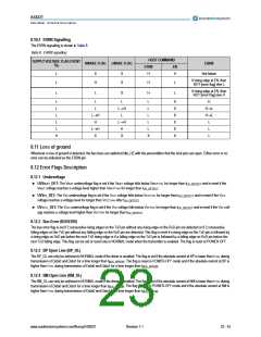
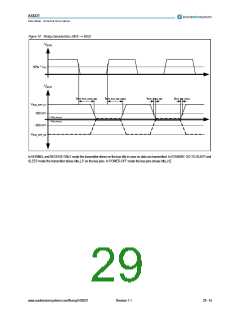
The error flags and the status flags can be read-out by applying a clock signal to pin EN in a non-low-power mode. A falling edge on pin EN starts
the read-out loading the content of the error/status flag into the shift register and signaling the error flag on the ERRN pin. On the second falling
edge the first flag (Bit 0) will be shifted out. The ERRN data is valid after tRO_EN_ERRN. If EN pin keeps on toggling after the last flag (Bit 15) the
next flag again is Bit 0. The complete list of bits is shown in Table 10. If no transition is detected on pin EN for longer than tRO_EN_TIMEOUT the
device enters the operation mode selected by the host pins.
Figure 10. Timing of the read-out mechanism
EN
50% VIO
ERRN
ERROR
FLAG
50% VIO
ERRN
Bit 0
Bit 1
Bit 2
ERRN
tRO_EN_ERRN
t < tRO_EN_TIMEOUT
t
> tRO_EN__TIMEOUT
8.14.1 Error and Status Flag Bit Order
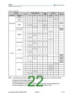
Table 10. Bit order for the read-out sequence
Bit
Description
Undervoltage VBAT detected
Undervoltage VIO detected
Undervoltage VCC detected
Bus error
Symbol
Bit 0
Bit 1
Bit 2
Bit 3
Bit 4
Bit 5
Bit 6
UVVBAT_DET
UVVIO_DET
UVVCC_DET
BUSERR
BP open line
BP_OL
BP short circuit to VCC
BP short circuit to GND
BP_VCC
BP_GND
www.austriamicrosystems.com/flexray/AS8221
Revision 1.1
25 - 43

 AMSCO [ AMS(艾迈斯) ]