AS8221
Data Sheet - Detailed Description
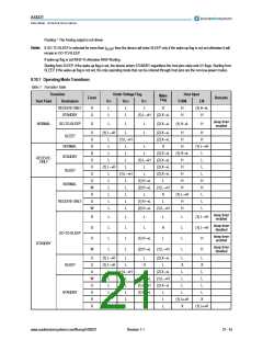
Floating = The Analog output is not driven
Note: If GO-TO-SLEEP is selected for more than tSLEEP then the device will enter SLEEP only if the wake-up flag is not set otherwise it will
remain in GO-TO-SLEEP.
If wake-up flag is set INH2=H otherwise INH2=floating.
Starting from SLEEP, if the wake-up flag is set, the device enters STANDBY regardless the host pins state and UV flags. Starting from
SLEEP, if the wake-up flag is not set, the only operating mode that can be entered through host pins are the non-low-power modes.
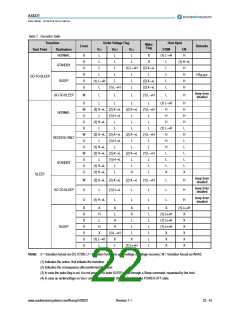
8.10.1 Operating Mode Transitions
Table 7. Transition Table
Transition
Under Voltage Flag
Host Input
Wake
Flag
Event
Remarks
Start Point
Destination
VIO
L
VBAT
VCC
STBN
EN
(1) H→L
H
RECEIVE-ONLY
STANDBY
S
U
L
L
X
H
H
L
L
L
(1) L→H
(2) X→L
sleep timer
enabled
NORMAL
GO-TO-SLEEP
S
L
L
L
(2) X→L
(1) H→L
H
U
U
S
(1) L→H
L
(2) X→L
(2) X→L
X
H
H
SLEEP
NORMAL
STANDBY
L
(1) L→H
H
H
L
L
L
H
(1) L→H
S
L
L
L
(2) X→L
(2) X→L
(2) X→L
(2) X→L
L
(1) H→L
L
L
L
L
H
H
L
L
L
RECEIVE-
ONLY
U
U
U
U
W
S
L
L
(1) L→H
L
H
(1) L→H
L
H
SLEEP
L
L
L
L
L
L
(1) L→H
L
H
L
L
L
L
L
(1) H→L
(2) H→L
L
H
NORMAL
(1) L→H
X
H
(1) L→H
RECEIVE-ONLY
GO-TO-SLEEP
U
W
(1) H→L
(2) H→L
L
H
H
(1) L→H
sleep timer
enabled
S
S
L
L
L
L
L
L
L
L
L
L
L
L
L
L
(1) L→H
sleep timer
disabled
L
H
L
(1) L→H
sleep timer
enabled
U
W
(1) H→L
(2) H→L
H
H
STANDBY
sleep timer
disabled
(1) L→H
U
U
U
W
U
U
S
(1) L→H
L
L
(2) X→L
L
L
SLEEP
(1) L→H
L
H
L
X
X
L
L
L
L
L
L
(1) L→H
L
(2) X→L
L
L
L
L
L
L
L
(2) X→L
(1) L→H
(1) H→L
H
(1) L→H
L
L
(2) X→L
L
L
STANDBY
L
L
L
L
(1) L↔H
X
L
X
S
H
(1) L↔H
www.austriamicrosystems.com/flexray/AS8221
Revision 1.1
21 - 43

 AMSCO [ AMS(艾迈斯) ]