AS8221
Data Sheet - Detailed Description
8.9 Fail Silent Behavior
8.9.1 RxEN / BGE timeout
In case no edges on RxEN and BGE within tTxEN_timeout are detected, the transmitter will stop transmitting the signals on RxD to the bus pins.
8.9.2 State Transitions due to Under Voltage Detection
ꢀ
ꢀ
ꢀ
ꢀ
In case of VBAT or VIO undervoltage is detected, SLEEP mode will be entered regardless the status of EN and STBN.
In case VCC undervoltage is detected, STANDBY mode will be entered regardless the status of EN and STBN.
VBAT and VIO undervoltage detection have higher priority than VCC undervoltage detection.
In case undervoltage at VBAT and VCC is detected, POWER-OFF mode is entered (bus state: Idle_HZ).
8.9.3 State Transitions due to Voltage Recovery Detection
ꢀ
If the voltage recovers the device will enter the mode selected by the EN and STBN pins, in case no undervoltage is present at the other
supply pins.
ꢀ
Starting from the POWER-OFF, the device enters the state selected by the host input pins (EN, STBN) only if VBAT or VCC recovers (VBAT
≥ VBATTHH or VCC ≥ VCCTHH) while VIO is available (undervoltage flag of VIO flag not set). If the VIO undervoltage flag is set, the STANDBY
mode will be entered. In both cases the Power-On flag is set.
ꢀ
If VBAT ≤ VBATTHL and VCC ≤ VCCTHL the device will be in POWER-OFF state, thus the bus wires are not terminated (bus state: Idle_HZ).
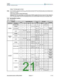
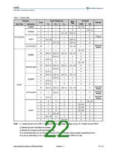
8.10 Mode Transitions
In case of power-off event, the device enters POWER-OFF regardless VIO undervoltage flag, wake-up flags and regardless the selection at the
host input pins.
Starting from the POWER-OFF the device enters STANDBY only in case a power on event occurs.
Starting from every operating mode the device enters SLEEP in case VBAT or VIO undervoltage flag is set regardless the VCC undervoltage flag,
the wake-up flag and the state of the host input pins.
Starting from every operating mode except SLEEP the device enters STANDBY in case VCC undervoltage flag is set and VBAT and VIO
undervoltage flags are not set, regardless the wake-up flag indication and the host input pins state.
Starting from a low-power mode the device enters the operation mode indicated by the host input pins if a wake-up event occurs.
In case all the undervoltage flags are reset the operation mode is selected by the wake-up flag and the host pins according to Table 6.
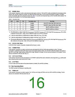
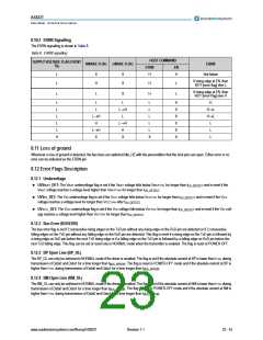
Table 6. Pin Signalling and Operating modes
Inputs
STBN
OutPut
Operation Mode
EN
RxD
ERRN
RxEN
INH1
INH2
L
L
Bus = Data_0
Bus = Active
H
H
H
NORMAL
NOT [Error flag]
H
H
H
H
Bus = Idle or Data_1
Bus = Idle
L
L
Bus = Data_0
Bus = Active
L
RECEIVE-ONLY
NOT [Error flag]
H
H
H
H
Bus = Idle or Data_1
Bus = Idle
L
L
L
X
H
L
GO-TO-SLEEP
STANDBY
NOT [Wake-up flag]
NOT [Wake-up flag]
NOT [Wake-up flag]
H
NOT [Wake-up flag]
NOT [Wake-up flag]
NOT [Wake-up flag]
L
NOT [Wake-up flag]
NOT [Wake-up flag]
NOT [Wake-up flag]
H
H
Floating
Floating
Floating
Floating
H
X
X
SLEEP
Floating
Floating
POWER-OFF
Where: H = Digital level high
L = Digital level low
x = Do not care
www.austriamicrosystems.com/flexray/AS8221
Revision 1.1
20 - 43

 AMSCO [ AMS(艾迈斯) ]