AS5050
Datasheet - Application Information
8.2 Placement of the Magnet
Non-Linearity Error over Displacement.
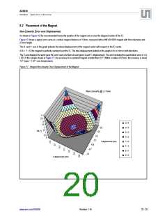
As shown in Figure 18, the recommended horizontal position of the magnet axis is over the diagonal center of the IC.
Figure 17 shows a typical error curve at a vertical magnet distance of 1.0mm, measured with a NdFeB N35H magnet with 6mm diameter and
2.5mm height.
The X- and Y- axis of the graph indicate the lateral displacement of the magnet center with respect to the IC center.
At X = Y = 0, the magnet is perfectly centered over the IC. The total displacement plotted on the graph is for ±1mm in both directions.
The Z-axis displays the worst case INL error over a full turn at each given X-and Y- displacement. The error includes the quantization error of ±½
LSB. At the sample shown in Figure 17, the accuracy for a centered magnet is better than 0.5°. Within a radius of 0.5mm, the accuracy is about
1.0° (spec = 1.41° over temperature).
Figure 17. Integral Non-linearity Over Displacement of the Magnet
Non-Linearity @ z=1mm
4
3.5
3
2.5
3.5-4
2
1.5
3-3.5
2.5-3
2-2.5
1.5-2
1-1.5
0.5-1
0-0.5
0.8
0.5
0.2
-0.1
-0.4
-0.7
INL [°]
1
0.5
0
Y-displacement [mm]
-1.0
X-displacement [mm]
www.ams.com/AS5050
Revision 1.16
20 - 25

 AMSCO [ AMS(艾迈斯) ]