AS5050
Datasheet - Package Drawings and Markings
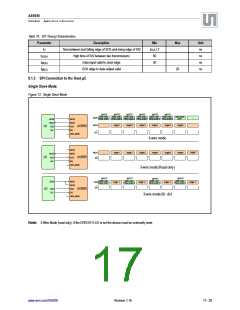
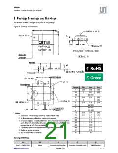
9 Package Drawings and Markings
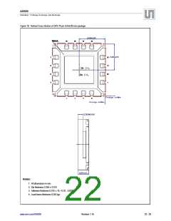
The device is available in a 16-pin QFN (4x4x0.85 mm) package.
Figure 18. Drawings and Dimensions
YYWWXZZ
AS5050 @
Symbol
A
Min
0.80
0
Nom
0.90
Max
1.00
0.05
A1
A3
L
0.02
0.20 REF
0.50
0.45
0
0.55
0.15
0.35
L1
b
-
0.25
0.30
D
4.00 BSC
4.00 BSC
0.65 BSC
2.40
E
e
D2
E2
aaa
bbb
ccc
ddd
eee
fff
2.30
2.50
Notes:
2.30
2.40
2.50
1. Dimensions and tolerancing conform to ASME Y14.5M-1994.
-
-
-
-
-
-
0.15
-
-
-
-
-
-
2. All dimensions are in millimeters. Angles are in degrees.
0.10
3. Dimension b applies to metallized terminal and is measured between 0.25mm
and 0.30mm from terminal tip. Dimension L1 represents terminal full back from
package edge up to 0.15mm is acceptable.
0.10
0.05
0.08
4. Coplanarity applies to the exposed heat slug as well as the terminal.
5. Radius on terminal is optional.
0.10
N
16
6. N is the total number of terminals.
Marking: YYWWXZZ.
YY
WW
X
ZZ
@
Year (i.e. 04 for 2004)
www.ams.com/AS5050
Week
Assembly plant identifier
Revision 1.16
Assembly traceability code
Sublot identifier
21 - 25

 AMSCO [ AMS(艾迈斯) ]