AS1310
Datasheet - Pin Assignments
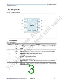
4 Pin Assignments
Figure 2. Pin Assignments (Top View)
1
2
3
4
8
7
6
5
LBI
GND
LX
VIN
EN
AS1310
LBO
REF
VOUT
Exposed pad
4.1 Pin Descriptions
Table 1. Pin Descriptions
Pin Number
Pin Name
Description
Low Battery Comparator Input. 0.6V Threshold. May not be left floating. If connected to GND, LBO is
working as Power Output OK.
1
LBI
Ground
2
3
4
5
6
GND
LX
External Inductor Connector.
Output Voltage. Decouple VOUT with a ceramic capacitor as close as possible to VOUT and GND.
Reference Pin. Connect a 100nF ceramic capacitor to this pin.
Low Battery Comparator Output. Open-drain output.
VOUT
REF
LBO
Enable Pin. Logic controlled shutdown input.
1 = Normal operation;
7
EN
0 = Shutdown; shutdown current <100nA.
Battery Voltage Input. Decouple VIN with a 22µF ceramic capacitor as close as possible to VIN and
GND.
8
9
VIN
NC
Exposed Pad. This pad is not connected internally. Can be left floating or connect to GND to achieve an
optimal thermal performance.
www.austriamicrosystems.com/DC-DC_Step-Up/AS1310
Revision 1.8
2 - 19

 AMSCO [ AMS(艾迈斯) ]