PI6049A Data Sheet
__________________________________________________________________________________________
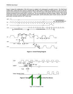
Figure 4 shows the initialization of the first sensor in relation to its subsequent cascaded sensors. The Start Input
Control (SIC) selects the first sensor to operate with 29 clock cycles of delay by connecting it to Vdd on the first
sensor and to Ground for all subsequent sensors. Hence the first sensor will operate with 29 inactive pixels being
clocked out before its first active pixel is clocked out. The rise and fall times are listed in table 5 above. The End of
Scan Pulse comes out in line with the second last active pixel, and the last active pixel of each sensor is the 344th
pixel which coincides with the 344th clock cycle.
GBST
Last pixel of preceding sensor
First pixel of succeding sensor
CLK
SO
2
3
4
1
1
2
3
26
27
28
29
30
31
32
33
34
35
36
VOUT
4
2
3
6
7
1
5
4
1
2
3
29 Inactive pixels (29 Clocks)
344 Active Pixels (344 Clocks)
CLKpw
CLKpw
CLKp
50%
CLK
Thold
CLKrt
CLKft
Tset
GBST
GRSTft
GRSTrt
prt
90%
pft
VOUT
10%
Figure 4. Overall Timing Diagram
CLK
1
2
30
29
31
32
Thold
Thold
Tset
GBST
Tset
Video Signal (Vout)
1
2
3
Figure 5. Timing of GBST-to-First Pixel of the First Sensor
Page 11 of 13, Revised 2-13-04

 AMI [ AMI SEMICONDUCTOR ]