Analog Microelectronics, Inc.
3-1/2 Digit A/D Converter - Low Power
With HOLD And Differential Reference Inputs
AME811/AME811A/AME811R
The A/D conversion has the following three phases:
1. Auto-Zero Phase
2. Integration Phase
1V below the V+. The integrator output can swing within
0.3 V of V+ or V- without increasing linearity errors.
Care must be exercised to make sure the integrator
output does not saturate. In a typical application, the
common mode is eliminated by connecting the INLO
to COM, Analog Common.
3. De-integration Phase
Auto-Zero Phase
The INHI and INLO are shorted to analog common in-
ternally. The reference capacitor is charged to the ref-
erence voltage. A feedback loop is closed around the
system to cancel the offset voltage of buffer, integrator
and comparator.
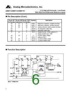
Differential Reference (VREF+ & VREF-)
The reference voltage can be generated anywhere
within the V+ to V-. Under a large common mode volt-
age, reference capacitor can gain charge during the
de-integration of a positive signal. The reference ca-
pacitor will lose charge when de-integrating a negative
input signal. The difference in reference voltage for
positive or negative input voltages can cause the
rollover error. To prevent rollover error from being in-
duced by large common-mode voltages, reference ca-
pacitor should be large compared to stray node capaci-
tance.
Signal Integration phase
The converter integrates the differential voltage across
the INHI and INLO for a fixed time, 1000 system clocks.
The polarity of the signal is determined at the end of
this phase.
Reference Integration Phase
INLO is internally connected to the Analog Common,
INHI is connected across the reference capacitor with
appropriate polarity determined by the control circuit.
The integrator output will then return to zero. The time
it takes to return to zero, 1000 x VIN /VREF, is the digi-
tal representation of the analog signal.
Analog Common (COM)
The Analog Common is to set a common mode volt-
age for the analog signal. The analog common is typi-
cally 3.0V below V+, set primary for the battery oper-
ated application. Analog common is capable to sink 20
mA. It’s source current is limited to 10 µA. Analog
common is therefore easily pulled to a more negative
voltage to override the internal reference. When sup-
ply voltage is greater than 7V, analog common can be
used as reference source with temperature coefficient
Differential Signal Inputs (INHI & INLO)
The AME811 has true differential inputs and accepts
input signals within the input common mode voltage
range (Vcm). Typical range is from 1V above the V- to
O
of typically 50 ppm/ C.
7

 AME [ ANALOG MICROELECTRONICS ]