AMD
VCC can rise to its steady state, two conditions are
required to ensure a valid power-up reset. These condi-
tions are:
POWER-UP RESET
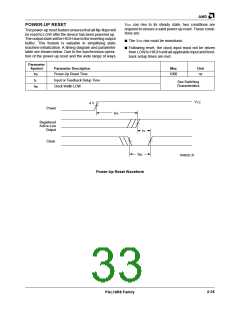
The power-up reset feature ensures that all flip-flops will
be reset to LOW after the device has been powered up.
The output state will be HIGH due to the inverting output
buffer. This feature is valuable in simplifying state
machine initialization. A timing diagram and parameter
table are shown below. Due to the synchronous opera-
tion of the power-up reset and the wide range of ways
■ The VCC rise must be monotonic.
■ Following reset, the clock input must not be driven
from LOW to HIGH until all applicable input and feed-
back setup times are met.
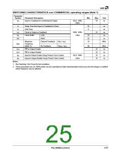
Parameter
Symbol
Parameter Description
Max
Unit
tPR
Power-Up Reset Time
1000
ns
tS
Input or Feedback Setup Time
Clock Width LOW
See Switching
Characteristics
tWL
VCC
4 V
Power
tPR
Registered
Active-Low
Output
tS
Clock
tWL
16492D-31
Power-Up Reset Waveform
2-35
PAL16R8 Family

 AMD [ AMD ]