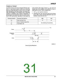
POWER-UP RESET
The MACH devices have been designed with the capa-
bility to reset during system power-up. Following
power-up, all flip-flops will be reset to LOW. The output
state will depend on the logic polarity. This feature pro-
vides extra flexibility to the designer and is especially
valuable in simplifying state machine initialization. A
timing diagram and parameter table are shown below.
Due to the synchronous operation of the power-up
reset and the wide range of ways V
steady state, two conditions are required to insure a
valid power-up reset. These conditions are:
can rise to its
CC
1. The V rise must be monotonic.
CC
2. Following reset, the clock input must not be driven
from LOW to HIGH until all applicable input and
feedback setup times are met.
Parameter Symbol
Parameter Descriptions
Power-Up Reset Time
Input or Feedback Setup Time
Clock Width LOW
Max
Unit
t
10
µs
PR
t
S
See Switching Characteristics
t
WL
V
CC
4 V
Power
t
PR
Registered
Output
t
S
Clock
t
WL
20405B-23
Power-Up Reset Waveform
MACH211SP-7/10/12/15/20
31

 AMD [ AMD ]