Descriptor DMA Transfers
of BWRITE has no effect in this configuration. See Fig-
ure 29.
The Am79C978 microcode will determine when a de-
scriptor access is required. A descriptor DMA read will
consist of two data transfers. A descriptor DMA write
will consist of one or two data transfers. The descriptor
DMA transfers within a single bus mastership period
will always be of the same type (either all read or all
write).
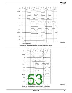
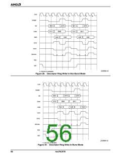
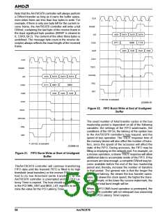
When SWSTYLE is set to 3, the descriptor entries are
ordered to allow burst transfers. TheAm79C978 con-
troller will perform all descriptor write operations in
burst mode, if BWRITE is set to 1. See Figure 30 and
Table 9 for the descriptor write sequence.
A write transaction to the descriptor ring entries is the
only case where the Am79C978 controller inserts a
wait state when being the bus master. Every data
phase in non-burst and burst mode is extended by one
clock cycle, during which IRDY is deasserted.
During descriptor read accesses, the byte enable sig-
nals will indicate that all byte lanes are active. Should
some of the bytes not be needed, then the Am79C978
controller will internally discard the extraneous informa-
tion that was gathered during such a read.
Note that Figure 28 assumes that the Am79C978 con-
troller is programmed to use 32-bit software structures
(SWSTYLE = 2 or 3). The byte enable signals for the
second data transfer would be 0111b, if the device was
programmed to use 16-bit software structures (SW-
STYLE = 0).
The settings of SWSTYLE (BCR20, bits 7-0) and
BREADE (BCR18, bit 6) affect the way the Am79C978
controller performs descriptor read operations.
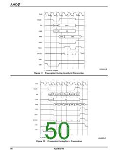
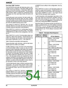
When SWSTYLE is set to 0 or 2, all descriptor read op-
erations are performed in non-burst mode. The setting
of BREADE has no effect in this configuration. See Fig-
ure 27.
Table 8. Descriptor Read Sequence
SWSTYLE
BCR20[7:0] BCR18[6]
BREADE
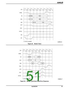
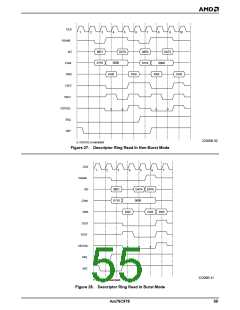
When SWSTYLE is set to 3, the descriptor entries are
ordered to allow burst transfers. TheAm79C978 con-
troller will perform all descriptor read operations in
burst mode, if BREADE is set to 1. See Figure 28.
AD Bus Sequence
Address = XXXX XX00h
Turn around cycle
Table 8 shows the descriptor read sequence.
Data = MD1[31:24], MD0[23:0]
Idle
0
X
During descriptor write accesses, only the byte lanes
which need to be written are enabled.
Address = XXXX XX04h
Turn around cycle
If buffer chaining is used, accesses to the descriptors
of all intermediate buffers consist of only one data
transfer to return ownership of the buffer to the system.
When SWSTYLE (BCR20, bits 7-0) is cleared to 0 (i.e.,
the descriptor entries are organized as 16-bit software
structures), the descriptor access will write a single
byte. When SWSTYLE (BCR20, bits 7-0) is set to 2 or
3 (i.e., the descriptor entries are organized as 32-bit
software structures), the descriptor access will write a
single word. On all single buffer transmit or receive de-
scriptors, as well as on the last buffer in chain, writes to
the descriptor consist of two data transfers.
Data = MD2[15:0], MD1[15:0]
Address = XXXX XX04h
Turn around cycle
Data = MD1[31:0]
Idle
2
X
Address = XXXX XX00h
Turn around cycle
Data = MD0[31:0]
Address = XXXX XX04h
Turn around cycle
Data = MD1[31:0]
Idle
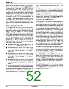
The first data transfer writes a DWord containing status
information. The second data transfer writes a byte
(SWSTYLE cleared to 0), or otherwise a word contain-
ing additional status and the ownership bit (i.e.,
MD1[31]).
3
3
0
1
Address = XXXX XX08h
Turn around cycle
Data = MD0[31:0]
The settings of SWSTYLE (BCR20, bits 7-0) and
BWRITE (BCR18, bit 5) affect the way the Am79C978
controller performs descriptor write operations.
Address = XXXX XX04h
Turn around cycle
Data = MD1[31:0]
Data = MD0[31:0]
When SWSTYLE is set to 0 or 2, all descriptor write op-
erations are performed in non-burst mode. The setting
54
Am79C978

 AMD [ AMD ]