AMD
P R E L I M I N A R Y
Writing a 1 to the Power Down bit of the ISA Power
Down bit of SIR3 will cause a request for a power down
to be generated to the 80188 core via an interrupt bit in
MIR0. The decision to power down will be made by the
80188 controller, and the actual power down command
will be executed by the 80188 controller by shutting off
thetransceiverandanyotherresourcesandthenwriting
to the power down command bit (PDC) of MIR0.
upper layers of the application and the Am79C930 de-
vice; and (2) the Am79C930 MAC firmware, which runs
on the embedded 80188 CPU, performs IEEE 802.11
(draft) MAC protocol functions and sends status infor-
mation to the device driver. The device driver communi-
cates with the Am79C930 device through the
system interface, usually by reading and writing to the
SRAM, with occasional accesses to Am79C930 device
registers. The Am79C930 device appears to the
device driver as a series of I/O mapped registers,
memory-mapped SRAM, and Flash memory. The MAC
firmware uses most of the Am79C930 device registers,
the SRAM, and the Flash memory to perform the IEEE
802.11 (draft) MAC functions. The Am79C930 device
driver also uses the SRAM to pass command and status
information to and from the Am79C930 device.
Writing a 0 to the Power Down bit of the PCMCIA Card
Configuration and Status Register will cause the Power
Down mode to be exited early by forcing the PDLC value
to 0. Because of this transition to 0, the PUCT value will
most likely not be encountered, and no power up ramp
time will occur (i.e., the PWRDWN signal will be deas-
serted at the same time that the CLKIN is reapplied to
the internal circuitry.).
Am79C930 System Interface Resources
Writing a 0 to the ISA Power Down bit of SIR3 will cause
the Power Down mode to be exited early by simulating
the effect of the Power Down Length Counter expiring.
Driver interaction with the Am79C930 device takes
place through the system interface.
The purpose of the Am79C930 device driver is to move
dataframesinandoutoftheAm79C930-basedwireless
communications system. The device driver will move
outgoing data frames into shared memory space and
then pass a command to the Am79C930 device indicat-
ing that the outgoing data is present and ready for trans-
mission. The device driver will respond to interrupts
from the Am79C930 device indicating that incoming
data has been placed into shared memory by the
Am79C930 device and is present and ready for proc-
essing by the device driver. The Am79C930 device also
uses the interrupt to indicate other changes in
Am79C930devicestatus. Commandsotherthan“trans-
mit” may be passed to the Am79C930 device by
the driver.
Writing a 1 to the Exit Power Down bit of SIR0 will cause
the Power Down mode to be exited early by forcing the
PDLC value to 0. Because of this transition to 0, the
PUCT value will most likely not be encountered, and no
power up ramp time will occur (i.e., the PWRDWN signal
will be deasserted at the same time that the CLKIN is
reapplied to the internal circuitry.).
Performing a CIS READ operation while the Am79C930
device is in the power down mode will cause an early
exit of the power down mode in exactly the same man-
ner as if the PCMCIA Card Configuration and Status
Register Power Down bit had been reset by writing a 0
to it.
Applicability to IEEE 802.11 Power Down Modes
In order to accommodate these basic functions of the
driver, theAm79C930deviceincludesanumberofcom-
mand and status registers as well as direct system inter-
face access to up to 128K of shared memory space
(SRAM). The device driver also has access to the 128K
ofFlashmemoryspacethatisusedtostorethefirmware
for the embedded 80188 core.
The power down functionality described above can be
applied to the IEEE 802.11 (draft) power down modes
by setting appropriate time values in the Power Down
Length Count register. This allows the Am79C930 de-
vice to power up at the IEEE 802.11 (draft) specified tim-
ing intervals in order to listen to the network for TIM and
DTIM messages. After listening for a specific amount of
time, the Am79C930 device can interrupt the driver soft-
ware with the intent of requesting the driver to re-initiate
the power down sequence. The free-running counter
can be used to calculate the proper Power Down Length
Count register values for each power down cycle.
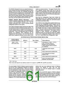
The following sections describe the resources available
to the device driver through the system interface. Later
sections will describe the resources available to the
MAC firmware through the 80188 embedded core.
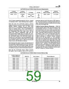
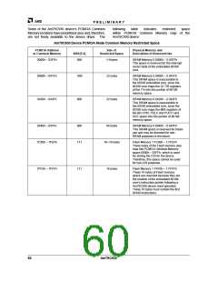
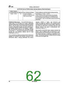
PCMCIA Mode Resources — The first table indicates
the range of I/O and memory addresses to which the
Am79C930 device will respond while operating in the
PCMCIA mode:
Software Access
TheAm79C930deviceisdirectlydrivenbytwopiecesof
software: (1) the device driver, which runs on the host
machine’s CPU, performs transfers of data between the
58
Am79C930

 AMD [ AMD ]