AMD
P R E L I M I N A R Y
mode, the host requests a power down by writing to the
Power Down bit (bit 2) of the PCMCIA Card Configura-
tion and Status Register. In the ISA Plug and Play mode,
the host requests a power down by writing to the ISA
Power Down bit, bit 7 of SIR3. In either case, the power
downrequestwillgenerateaninterrupttothe80188em-
bedded core. In response to the interrupt, the 80188
core should be programmed to perform a power down
sequence, as follows:
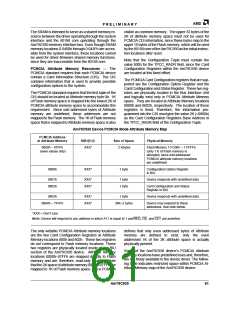
If the Am79C930 device is operating in the ISA Plug and
Play mode, then SIR0, SIR1, SIR2, and SIR3 registers
will be the only locations that are still accessible when
theAm79C930deviceisinthepowerdownmode. SIR4,
SIR5, SIR6, and SIR7, Plug and Play registers, and
SRAM and Flash memory locations will not be accessi-
ble in the power down mode when ISA Plug and Play
mode has been selected. This means that Plug and Play
state changes will not be possible in the power
down mode.
To power down the Am79C930 device, the 80188 core
should write a time value to the Power Down Length
Count registers. This time value is the intended duration
of the power down period. Then the 80188 core should
write a time value to the Power Up Clock Timer regis-
ters. This time value is the time needed for the buffered
CLKIN signal to return to stable operation from a
stopped state. Then the 80188 core should write to ap-
propriate TIR registers to power down the transceiver.
The 80188 core should now signal an interrupt to the
host that it is about to enter the power down mode. This
communication is necessary, since some of the
Am79C930 system resources will not be available dur-
ing power down mode, and the driver should not attempt
accesses to the unavailable resources, or else an unac-
ceptably long waiting period will occur before the
Am79C930 device finally wakes up and responds to the
access. The host should respond to the
80188-generated interrupt, and the 80188 will respond
by writing a 1 to the Power Down bit in the Processor In-
terface Register (MIR0). The Power Down command
will cause the internally routed CLKIN signal to the
80188 and the TAI to stop running, thereby, bringing the
80188 itself into a power savings mode. At this point in
the sequence, the driver software will no longer have ac-
cess to the SRAM and Flash memory devices. Only the
PCMCIA CCR registers and SIR0, SIR1, SIR2 and SIR3
will remain accessible to the host.
When the power down command is executed, the clock
to most of the circuits of the device is suspended while
power is maintained, such that all state information is
preserved. Outputs that were driving active high or ac-
tive low signals at the time of execution of the power
down command will continue to hold in the state that
they were in at the time of execution of the power down
command. Outputs that were held in a high impedance
state will remain in a high impedance state. Note that
some outputs may still change state, as some sections
of the device are not affected by power down (e.g., the
system interface signals that are used to access the
PCMCIA configuration registers and SIR0, SIR1, SIR2,
and SIR3). Transitions on device inputs which lead to
circuits that are affected by the power down will not be
seen by the circuit, since the circuit is powered down.
Whenthepowerdownmodeisexited, theinternallysus-
pended clock will resume and logical operations will
continue from the point of suspension with no loss of
state information.
When the Power Down Length Counter reaches the
value of the Power Up Clock Timer, then the PWRDWN
output will be deasserted. When the Power Down
Length Counter reaches 0, then the signal on the CLKIN
input to the Am79C930 will once again be sent to all
parts of the device. The time between the deassertion of
PWRDWNandthereapplicationoftheCLKINtointernal
circuits allows the clock to stabilize before it is distrib-
uted to the 80188 core and the TAI.
When the power down command is executed, the
PWRDWNoutputwillbecomeactive. Thisoutputcanbe
used to power down additional devices which are part
of the entire Am79C930-based subsystem, such as a
radio transceiver. (Note that the CLKIN clock signal to
internal Am79C930 circuits will be gated off inside of the
Am79C930 device, even when the external oscillator
continues to drive the Am79C930 CLKIN input.)
A discrete power up timer, which would indicate the time
duration that the Am79C930 device should remain
awake, is not included in the Am79C930 device, but a
firmware implementation of such a function is possible
byusingtheFreecountofMIR5, MIR6, andMIR7and/or
80188 controller timers.
In the power down mode, slave accesses to the
Am79C930 device will become limited to the PCMCIA
Card Configuration Option Register, the PCMCIA Card
Configuration and Status Register, and SIR0, SIR1,
SIR2, and SIR3 if the Am79C930 device is in PCMCIA
mode. All other registers will be inaccessible, including
SRAM and Flash memory locations either through the
memory window or through SIR4, SIR5, SIR6, or SIR7.
(Note that a CIS READ operation will cause power down
exit, but will proceed normally.)
Writing a 1 to the Power Down bit of the PCMCIA Card
Configuration and Status Register will cause a request
for a power down to be generated to the 80188 core via
an interrupt bit in MIR0. The decision to power down will
be made by the 80188 controller, and the actual power
down command will be executed by the 80188 controller
by shutting off the transceiver and any other resources
and then writing to the power down command bit (PDC)
of MIR0.
Am79C930
57

 AMD [ AMD ]