QUAD GIGABIT ETHERNET TRANSCEIVER
S2066
Table 18. S2066 Receiver Timing
Parameters
Description
Min
Max Units
Conditions
Measured +.8V to +2.0V. See
Figure 17.
TRCR, TRCF
RBC1, RBC0 Rise and Fall Time
-
3.0
3.0
175
ns
ns
µs
Measured +.8V to +2.0V. See
Figure 16.
TDR, TDF
Data Output Rise and Fall Time
TLOCK
(Frequency)
Frequency Acquisition Lock Time
(Loss of Lock) (1.25 Gbps)
-
After power up.
TJ
Total Input Jitter Tolerance
599
370
-
-
ps
ps
As specified in IEEE 802.3z.
As specified in IEEE 802.3z.
TDJ
Deterministic Input Jitter Tolerance
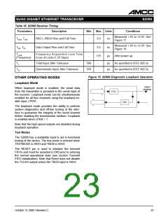
Figure 15. S2066 Diagnostic Loopback Operation
OTHER OPERATING MODES
Loopback Mode
output
disabled
When loopback mode is enabled, the serial data
from the transmitter is provided to the serial input of
the receiver. Loopback mode can be simultaneously
enabled for all four channels using the loopback-en-
able input, LPEN.
CSU
CRU
The loopback mode provides the ability to perform
system diagnostics and off-line testing of the inter-
face to guarantee the integrity of the serial channel
before enabling the transmission medium. Loopback
is enabled when LPEN = 1.
Note that the high speed outputs are disabled during
loopback operation.
Test Modes
The S2066 has a testability input to aid in functional
testing of the device. The test mode is entered when
TESTMODE is HIGH and TBCB is HIGH.
The RESET pin is used to initialize the transmit
FIFOs and must be asserted (LOW) prior to entering
the normal operational state (see section Transmit
FIFO Initialization). Note that Reset does not disable
the TCLKO output unless the TBCB input is HIGH.
23
October 13, 2000 / Revision C

 AMCC [ APPLIED MICRO CIRCUITS CORPORATION ]