7–8
Chapter 7: Package Information
Package Outlines
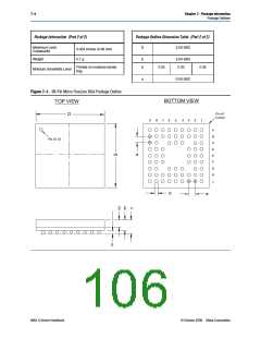
Figure 7–3. 100-Pin Micro FineLine BGA Package Outline
BOTTOM VIEW
TOP VIEW
D
Pin A1
Corner
11 10
9
8
7
6
5
4
3
2
1
A
B
C
D
E
F
Pin A1 ID
G
H
J
K
L
e
b
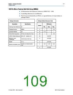
100-Pin FineLine Ball-Grid Array (FBGA)
■
■
■
All dimensions and tolerances conform to ASME Y14.5 – 1994
Controlling dimension is in millimeters
Pin A1 may be indicated by an ID dot, or a special feature, in its proximity on
package surface
Package Information
Package Outline Dimension Table
Description
Specification
Millimeters
Nom.
Symbol
Ordering Code Reference
F
Min.
Max.
Package Acronym
Substrate Material
FBGA
BT
A
—
—
—
1.55
—
A1
0.25
MAX II Device Handbook
© October 2008 Altera Corporation

 ALTERA [ ALTERA CORPORATION ]