Chapter 17: Understanding and Evaluating Power in MAX II Devices
17–13
Power Estimation Summary
Power Estimation Summary
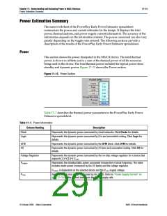
The main worksheet of the PowerPlay Early Power Estimator spreadsheet
summarizes the power and current estimates for the design. It displays the total
power, thermal analysis, and power supply current information. The accuracy of the
information depends on the information entered. The power consumed can also vary
greatly depending on the toggle rates entered. The following sections provide a
description of the results of the PowerPlay Early Power Estimator spreadsheet.
Power
This section shows the power dissipated in the MAX II device. The total thermal
power is shown in mWatts and is a sum of the thermal power of all the resources
being used in the device. The total thermal power includes the typical power from
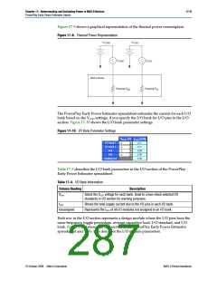
standby and dynamic power. Figure 17–13 shows the Power section.
Figure 17–13. Power Section
Table 17–7 describes the thermal power parameters in the PowerPlay Early Power
Estimator spreadsheet.
Table 17–7. Power Information
Column Heading
Description
Clock
Logic
Represents the dynamic power consumed by clock networks. Click Clocks for details.
Represents the dynamic power consumed by LEs and associated routing. Click Logic for
details.
UFM
I/O
Represents the dynamic power consumed by the UFM block. Click UFM for details.
Represents the dynamic power consumed by I/O pins and associated routing. Click I/O for
details.
Voltage Regulator
PSTANDBY
Represents the dynamic power consumed by the on-chip voltage regulator for a device that
supports 2.5-V/3.3-V VCCINT
.
Represents the standby/static power consumed irrespective of clock frequency. The value
includes static power consumed by the I/O banks and the voltage regulator.
P
STANDBY is dependent on the selected device and the VCCINT supply voltage.
Represents the total power consumed by the CPLD. Refer to “Power Supply Current” on
page 17–15 for the current draw from the CPLD supply rails.
PTOTAL
© October 2008 Altera Corporation
MAX II Device Handbook

 ALTERA [ ALTERA CORPORATION ]