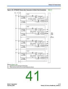
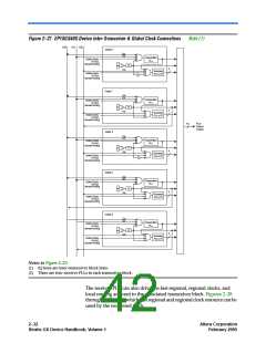
Figure 2–27. EP1SGX40G Device Inter-Transceiver & Global Clock Connections
Note (1)
IQ0
IQ1
IQ2
Quad 0
IQ0
IQ1
Transmitter
PLL
Global Clocks,
I/O Bus,
General Routing
/2
4
IQ2
Receiver
PLLs (1)
Global Clocks,
I/O Bus,
General Routing
Quad 1
Quad 4
Quad 2
IQ0
IQ1
Transmitter
PLL
Global Clocks,
I/O Bus,
General Routing
/2
/2
/2
4
4
4
IQ2
Receiver
PLLs (1)
Global Clocks,
I/O Bus,
General Routing
16
PLD
Global
Clocks
IQ0
IQ1
Transmitter
PLL
Global Clocks,
I/O Bus,
General Routing
IQ2
Receiver
PLLs (1)
Global Clocks,
I/O Bus,
General Routing
IQ0
IQ1
Transmitter
PLL
Global Clocks,
I/O Bus,
General Routing
IQ2
Receiver
PLLs (1)
Global Clocks,
I/O Bus,
General Routing
Quad 3
IQ0
IQ1
Transmitter
PLL
Global Clocks,
I/O Bus,
General Routing
/2
4
IQ2
Receiver
PLLs (1)
Global Clocks,
I/O Bus,
General Routing
Notes to Figure 2–27:
(1) IQ lines are inter-transceiver block lines.
(2) There are four receiver PLLs in each transceiver block.
The receiver PLL can also drive the fast regional, regional clocks, and
local routing adjacent to the associated transceiver block. Figures 2–28
through 2–31 show which fast regional and regional clock resource can be
used by the recovered clock.
2–32
Stratix GX Device Handbook, Volume 1
Altera Corporation
February 2005

 ALTERA [ ALTERA CORPORATION ]